Splicing and connectorization of photonic crystal fibers

a technology of photonic crystal fibers and connectors, applied in the field of optical fibers, can solve the problems of poor mechanical strength, high splice loss, and difficult transition from small core pcfs to standard optical fibers, and achieve the effect of low loss and low loss

Inactive Publication Date: 2007-05-31
NKT PHOTONICS
View PDF25 Cites 19 Cited by
  • Summary
  • Abstract
  • Description
  • Claims
  • Application Information

AI Technical Summary

Benefits of technology

[0011] Tapering of PCF may be used to provide low loss transition coupling from PCF to standard optical fibres (see e.g. WO00049435 or EP01199582). However, tapering is time-consuming and laborious work involving manufacturing of tapered optical fibre regions. Furthermore, due to significantly reduced fibre diameter (typically a few tens of micrometers), the strength of optical fibres with tapered regions is lower than for un-tapered optical fibres.
[0136] Within the present context it is intended that the term “spliceable optical fibre” is interpreted broadly to include the ability of an optical fibre to be spliced to another optical fibre or to be connected to another optical component, e.g. a connector, thereby ensuring coupling of the transmitted light to said other optical fibre or said other optical component with a reduced loss of light.

Problems solved by technology

Transition from small core PCFs to standard optical fibers is generally difficult.
Splice losses are typically high (≧0.3 dB—see e.g. Hansen et al., “Highly Nonlinear Photonic Crystal Fiber with Zero-Dispersion at 1.55 μm” Optical Fiber Communication Conference 2002 post deadline paper, 2002), and the mechanical strength is poor when short term heating (sometimes referred to as “cold” splices) is used.
However, tapering is time-consuming and laborious work involving manufacturing of tapered optical fibre regions.

Method used


Image

  • Splicing and connectorization of photonic crystal fibers
  • Splicing and connectorization of photonic crystal fibers
  • Splicing and connectorization of photonic crystal fibers

Examples


Embodiment Construction

[0159] In order to explain the invention in more detail, the proceeding description shall be based on examples. The examples illustrate the concepts and design ideas that underlie the invention. It is to be understood that the examples are merely illustrative of the many possible specific embodiments which can be devised from the present invention as well as there exists many possible applications that may be devised from the principles of the invention. The presented examples are not intended to limit the scope of the invention.

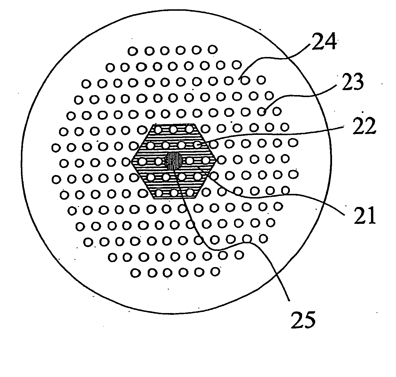
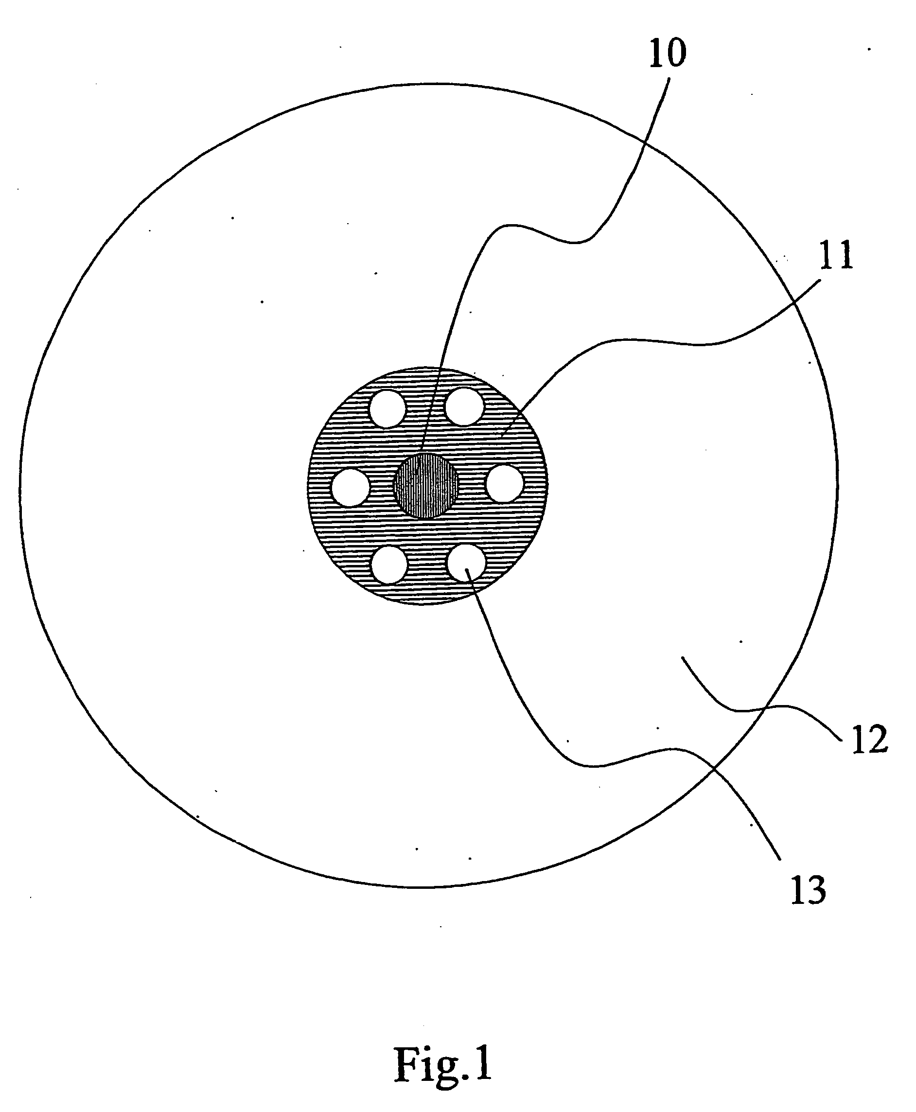
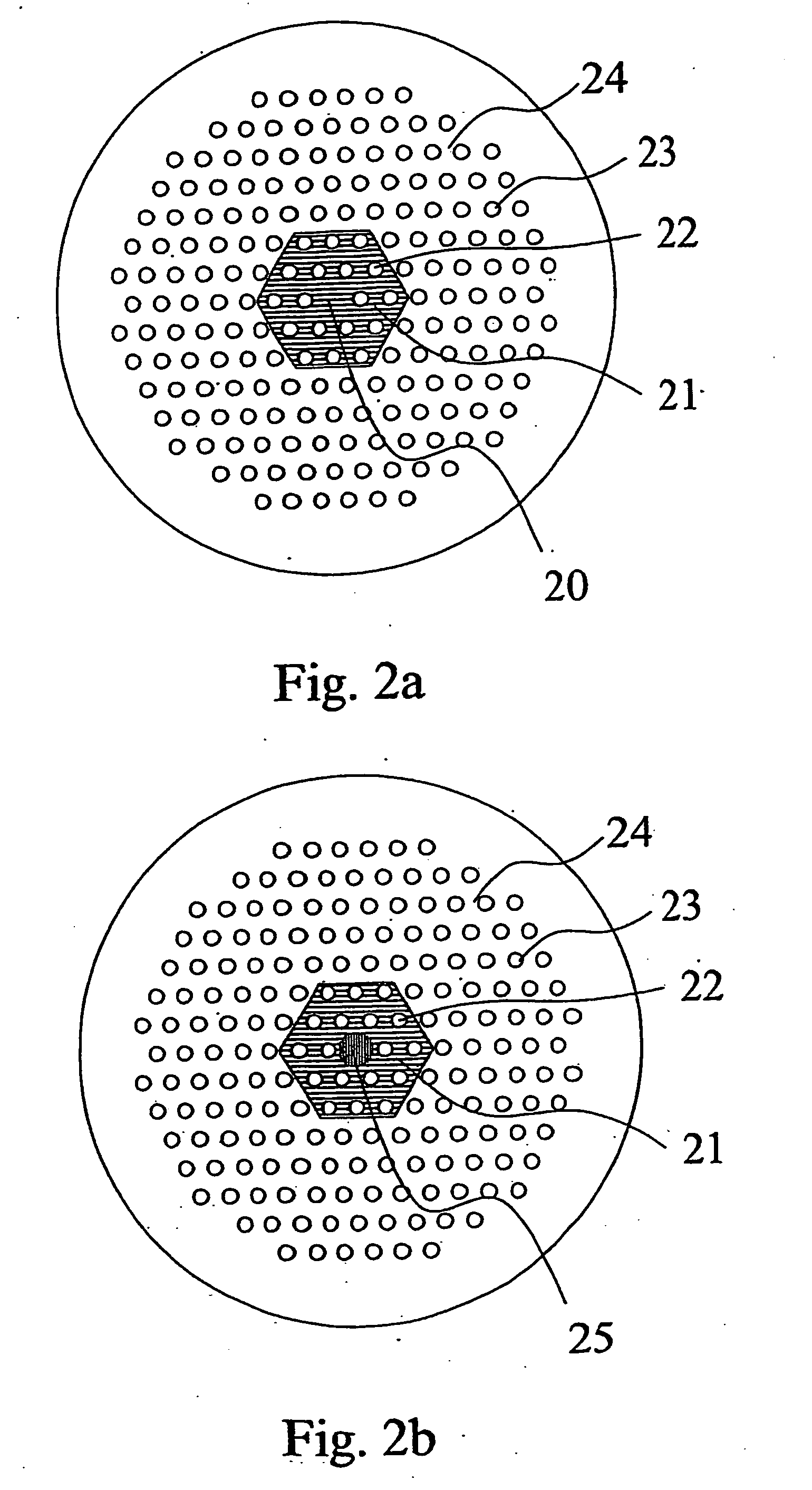
[0160] The present invention discloses in a preferred embodiment a spliceable optical fibre, of which a cross sectional view perpendicular to a longitudinal direction of the fibre is shown schematically in FIG. 1. The fibre is a photonic crystal fibre comprising a core region 10 and a cladding region, the cladding region comprising an inner cladding region 11 and an outer cladding region 12. The inner cladding region comprises low-index inner cladding featu...


PUM

PropertyMeasurementUnit
diameteraaaaaaaaaa
diameteraaaaaaaaaa
lengthaaaaaaaaaa

Abstract

A method of coupling a spliceable optical fibre for transmission of light in its longitudinal direction to an optical component, the method comprising (A) providing the spliceable optical fibre, said spliceable optical fibre comprising: (a) a core region; and (b) a microstructured cladding region, said cladding region surrounding said core region and comprising: (bI) an inner cladding region with inner cladding features arranged in an inner cladding background material with a refractive index n1, said inner cladding features comprising thermally collapsible holes or voids, and (b2) an outer cladding region with an outer cladding background material with a refractive index n2; said spliceable optical fibre having at least one end; (B) collapsing said thermally collapsible holes or voids by heating said least one end of said spliceable optical fibre; and (C) coupling said collapsed spliceable optical fibre end to the optical component. A spliceable optical fibre; a preform for producing a spliceable optical fibre; a method of producing a spliceable optical fibre comprising drawing of the preform; a heat-treated spliceable optical fibre; an article comprising a spliceable optical fibre is further disclosed.

Description

1. BACKGROUND OF THE INVENTION [0001] The present invention relates to a method of coupling a spliceable optical fibre to an optical component; a spliceable optical fibre; a preform for producing a spliceable optical fibre; a method of producing a spliceable optical fibre comprising drawing of the preform; a heat-treated splice able optical fibre; an article comprising a spliceable optical fibre. [0002] 1. The Technical Field [0003] In recent years a new class of optical fibres has appeared. The optical guiding mechanism in these fibres is provided by introducing a number of holes or voids in the optical fibres. These holes typically run parallel with the fibre and extend along the fibre length. Such fibres are generally described by A. Bjarklev et al. in “Photonic Crystal Fibres”, Kluwer Academic Publishers, 2003 (ISBN 1-4020-7610-X), which is referred to in the following as [Bjarklev et al.]). [0004] The light guiding principle can either be based on Total Internal Reflection (TIR...

Claims


Application Information

Patent Timeline
Patent Type & Authority Applications(United States)
IPC IPC(8): G02B6/032G02B6/02G02B6/255
CPCG02B6/02328G02B6/02333G02B6/02347Y10T29/49826G02B6/02376G02B6/02385G02B6/255G02B6/02357
Inventor BROENG, JESKRISTIANSEN, RENE ENGEL
Owner NKT PHOTONICS
Why Eureka
Try Eureka