Multi-stage system for selective catalytic reduction

a catalytic reduction and multi-stage technology, applied in the direction of machines/engines, process and machine control, arsenic compounds, etc., can solve the problems of nox not being reduced, requiring significant space, and difficulty in matching the quantity of ammonia and nox flowing into the scr system

Inactive Publication Date: 2007-05-31
CATERPILLAR INC
View PDF44 Cites 88 Cited by
  • Summary
  • Abstract
  • Description
  • Claims
  • Application Information

AI Technical Summary

Problems solved by technology

However, it may be difficult to match the quantities of ammonia and NOx flowing into the SCR system.
Further, even when the ratios are perfectly matched, some of the NOx may not be reduced due to inadequate mixing, short exhaust gas transit times, or sub-optimal catalyst operating conditions.
For example, the system of the '642 publication may require on-board storage of reductants, which may require significant space and may be hazardous.
Further, the system of the '642 publication may use more reductant than is needed, thereby wasting chemicals and potentially releasing the reductant into the environment.
Further, the system of the '642 publication may not provide optimum NOx-emissions control for some applications.

Method used


Image

  • Multi-stage system for selective catalytic reduction
  • Multi-stage system for selective catalytic reduction
  • Multi-stage system for selective catalytic reduction

Examples


Embodiment Construction

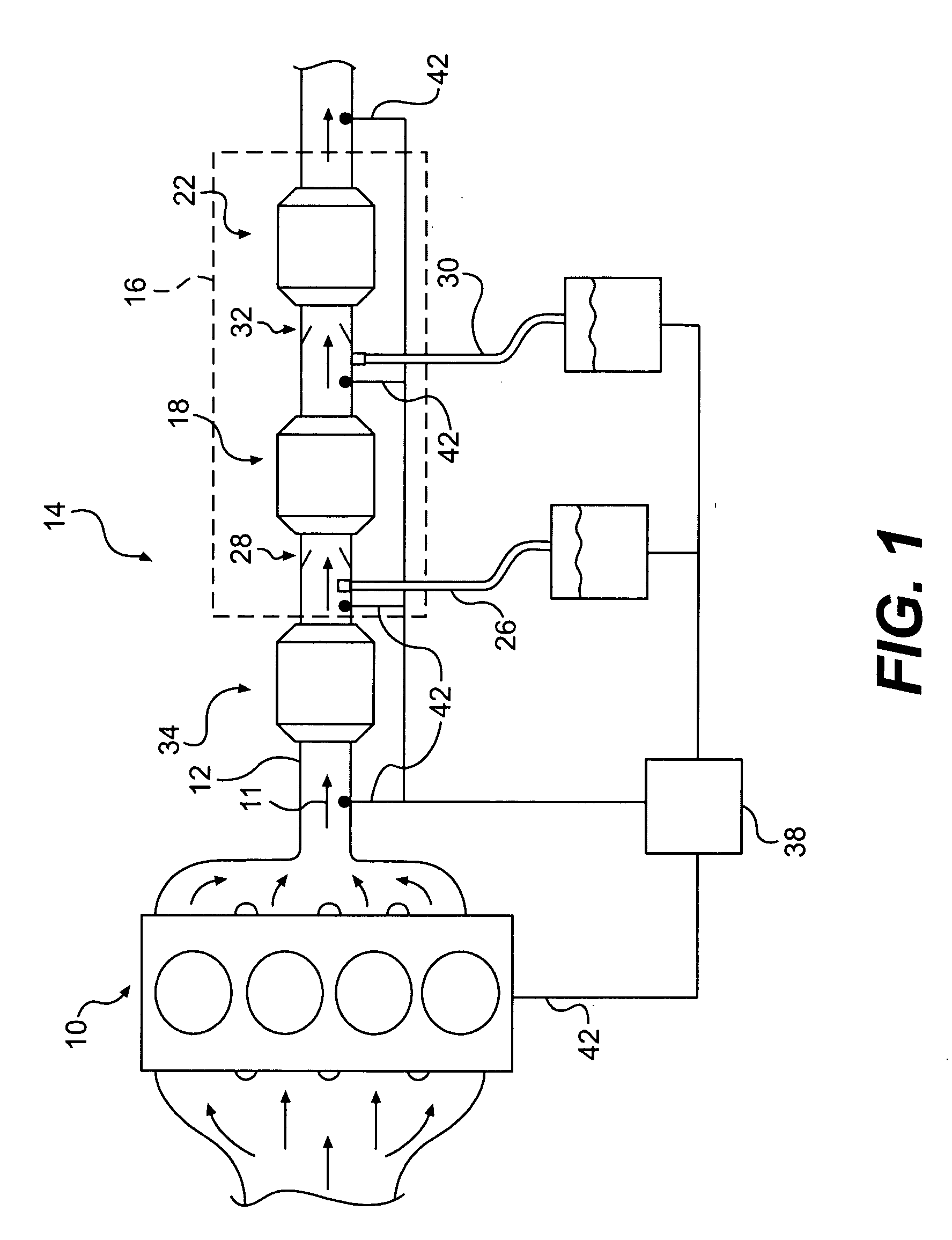
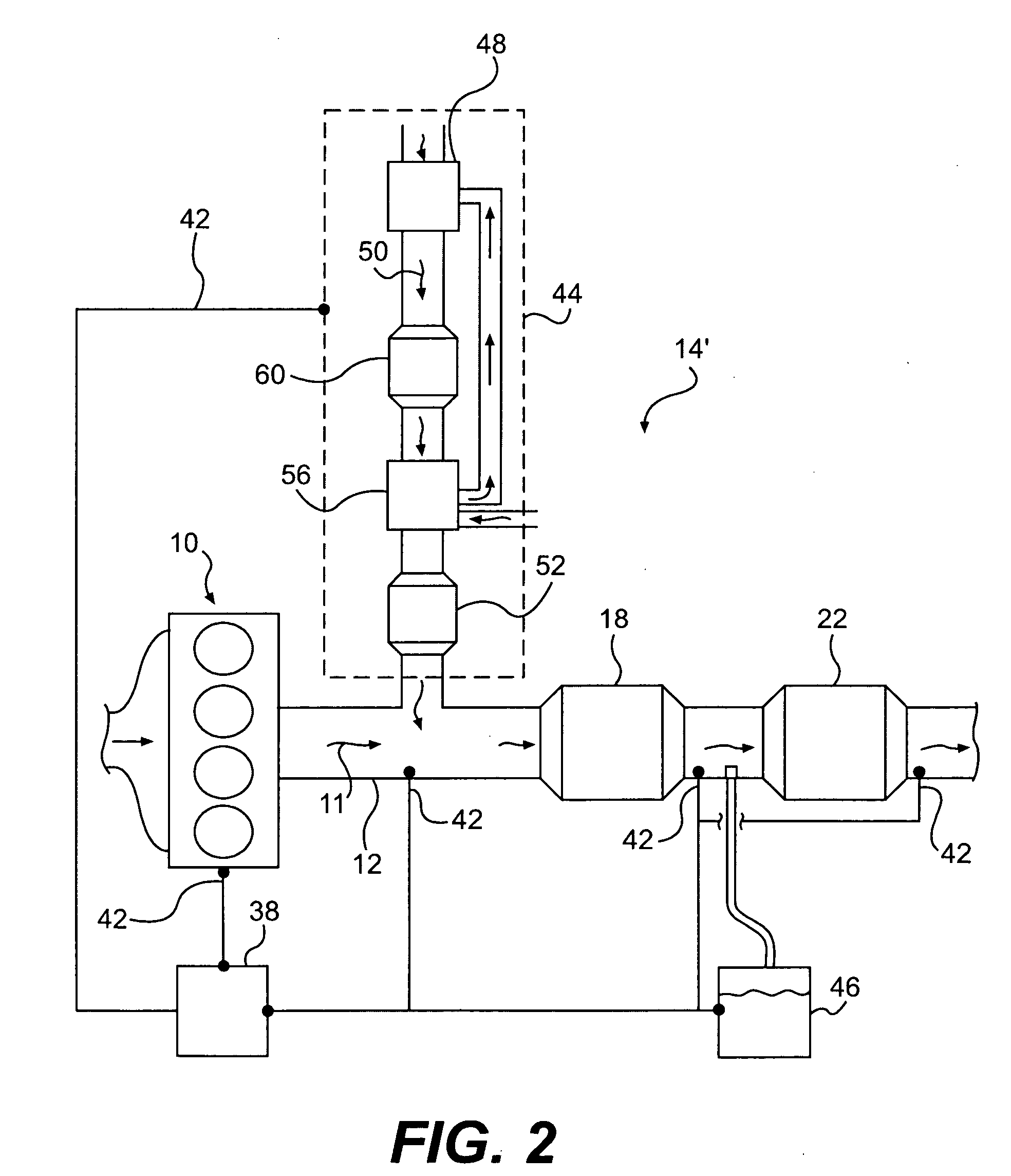
[0015]FIG. 1 illustrates an engine 10 and exhaust system 14 including a selective catalytic reduction (SCR) system 16, according to an exemplary disclosed embodiment. Combustion within engine 10 may produce a NOx-containing exhaust gas stream 11, which may flow into an exhaust passage 12 of exhaust system 14. Exhaust stream 11 may flow downstream toward catalysts 18, 22 of SCR system 16.

[0016] SCR system 16 may include multiple SCR catalysts 18, 22 and multiple ammonia supply systems 26, 30. As shown, first SCR catalyst 18 and second SCR catalyst 22 may be in fluid communication with exhaust passage 12, and second SCR catalyst 22 may be disposed downstream of first SCR catalyst 18. Further, first ammonia supply system 26 may be configured to supply ammonia to exhaust passage 12 upstream of first SCR catalyst 18, and second ammonia supply system 30 may be configured to supply ammonia to exhaust passage 12 downstream of first SCR catalyst 18 and upstream of second SCR catalyst 22.

[0...


PUM

PropertyMeasurementUnit
temperaturesaaaaaaaaaa
temperatureaaaaaaaaaa
operating temperatureaaaaaaaaaa

Abstract

A first aspect of the present disclosure includes a method of controlling nitric oxides emissions. The method may include producing an exhaust gas stream containing NOx and supplying the exhaust gas stream to an exhaust passage. The method may further comprise supplying ammonia to the exhaust passage at a location upstream of a first selective catalytic reduction catalyst, wherein the amount of ammonia supplied at the first location is less than about 90% of the effective amount of ammonia needed for reduction of all NOx at the first location. Further, ammonia may be supplied to the exhaust passage at a second location downstream of the first selective catalytic reduction catalyst and upstream of a second selective catalytic reduction catalyst.

Description

TECHNICAL FIELD [0001] This disclosure pertains generally to exhaust-gas purification systems, and more particularly, to selective catalytic reduction systems with multiple catalysts. BACKGROUND [0002] Selective catalytic reduction (SCR) provides a method for removing nitrogen oxides (NOx) emissions from fossil fuel powered systems for engines, factories, and power plants. During SCR, a catalyst facilitates a reaction between exhaust ammonia and NOx to produce water and nitrogen gas, thereby removing NOx from the exhaust gas. Generally, the exhaust gas ammonia is mixed with an exhaust gas stream upstream of an SCR catalyst. The ammonia may be supplied directly into the exhaust gas stream or provided as urea, which can be converted to ammonia under appropriate conditions. [0003] To optimize NOx removal from the exhaust gas stream, while preventing release of potentially noxious ammonia or urea, the NOx and ammonia are generally supplied at approximately one-to-one ratios. However, it...

Claims


Application Information

Patent Timeline
Patent Type & Authority Applications(United States)
IPC IPC(8): B01D53/56B01D50/00B01D53/34B32B27/02
CPCB01D53/90B01D53/9409B01D53/9431B01D53/9477B01D2251/2062F01N3/04F01N3/05F01N3/2053F01N3/2066F01N3/2073F01N13/107F01N2240/25F01N2610/02F02B37/00Y10S423/05Y02T10/24F01N13/009F01N13/011F01N13/0093Y02A50/20Y02T10/12
Inventor DRISCOLL, JAMES JOSHUAMILAM, DAVID M.
Owner CATERPILLAR INC
Why Eureka
Try Eureka