Single device to create flame and extinguish flame

a single device and flame extinguishing technology, applied in extinguishing devices, burners, combustion types, etc., can solve the problems of reducing available oxygen, affecting the combustion process, so as to reduce available oxygen and reduce lingering odors.

Inactive Publication Date: 2007-05-31
BLOOMFIELD JOHN W
View PDF28 Cites 12 Cited by
  • Summary
  • Abstract
  • Description
  • Claims
  • Application Information

AI Technical Summary

Benefits of technology

[0014] The present invention declares methods and means to extinguish candles or other small, desired and controlled flames that is part of and embodied in conventional and popular lighters. Some lighters are utilize stored fuel. Those fuels can be butane or other low pressure combustible liquids and gases that are released by valves and delivered via capillary tubes. Others are combustible liquids that wick up a suitable material to be presented to atmosphere. Igniting methods include mechanical sparking of materials capable and possessing those attributes that produce sparks such as flints or similar compound derivatives. Other igniting methods include electronic excitation to cause a high voltage sufficient to result in a physical spark between electrodes. All of these methods and means are well known and are produced as “lighters” by the billions, annually, worldwide. They are produced in a variety of shapes, colors, lengths, sizes, child proof mechanisms and schemes, designs and combinations with other art.
[0015] One method and means to extinguish a flame with a chemical compound that reduces the available oxygen around the flame to a level that is insufficient to support the flame. The compound can either possess attributes that replace available oxygen or chemically bind available oxygen and thereby reducing said oxygen to an insufficient level to support the flame. These various and commercially available compounds may be found in several forms. One form may be that of liquids under low pressure that evaporate to a gaseous state when released to atmosphere. The release of the gas may extinguish the flame by one or combination of both of the two methods previously outlined. That is, (1) reduce available oxygen; (2) disrupt the flame boundary layer and cool the fuel.
[0016] The extinguishing gas is stored in a vessel integrated into the lighting device. The storage vessel may be in the handle as is the butane in standard lighters. It may be adjacent to or imbedded in the handle and the extension wand. The delivery of the gas to the flame area is controlled by means of a valve. Said valve may be a separate valve operated by a trigger or a button or other digitally and manually activated means. The same igniting trigger or mechanism may be used by means of a switching mechanism that switches to the desired function. Said valve or valves and operative means is part of the lighter device. The delivery from the valve may be via a capillary tube extending to the end of the lighter device. Said capillary tube may be separate from the capillary tube utilized for t...

Problems solved by technology

That is, (1) reduce available oxygen; (2) d...

Method used


Image

  • Single device to create flame and extinguish flame
  • Single device to create flame and extinguish flame
  • Single device to create flame and extinguish flame

Examples


Embodiment Construction

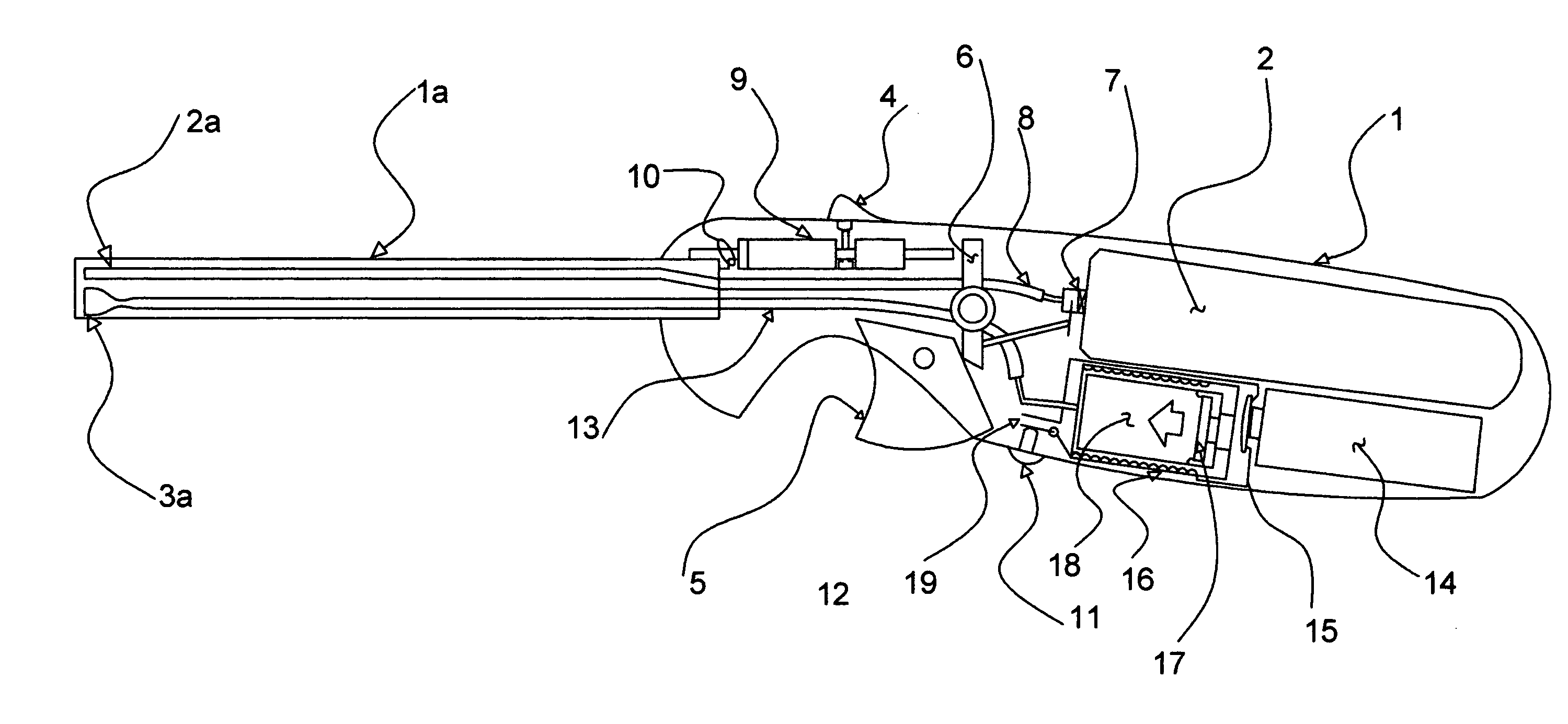
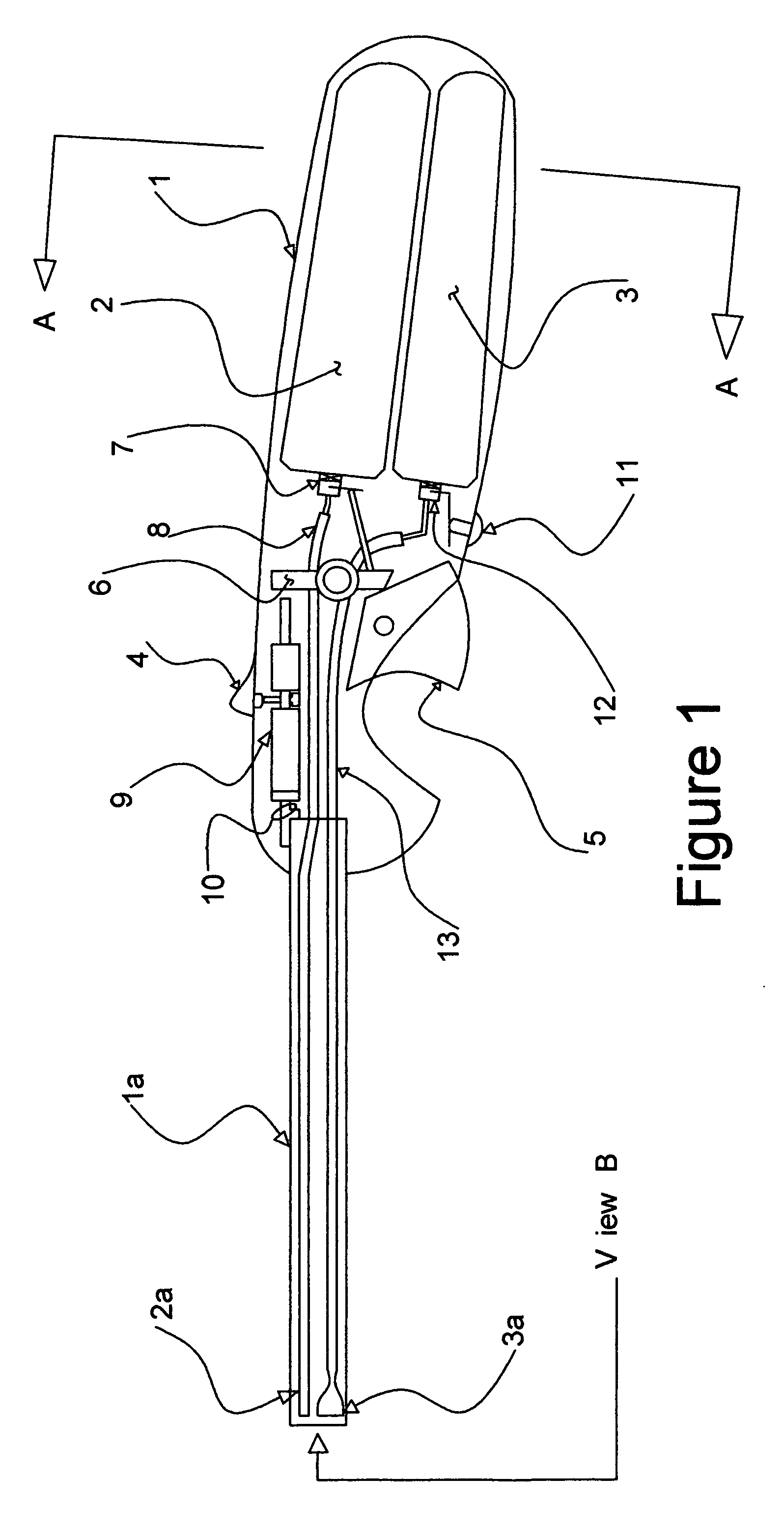
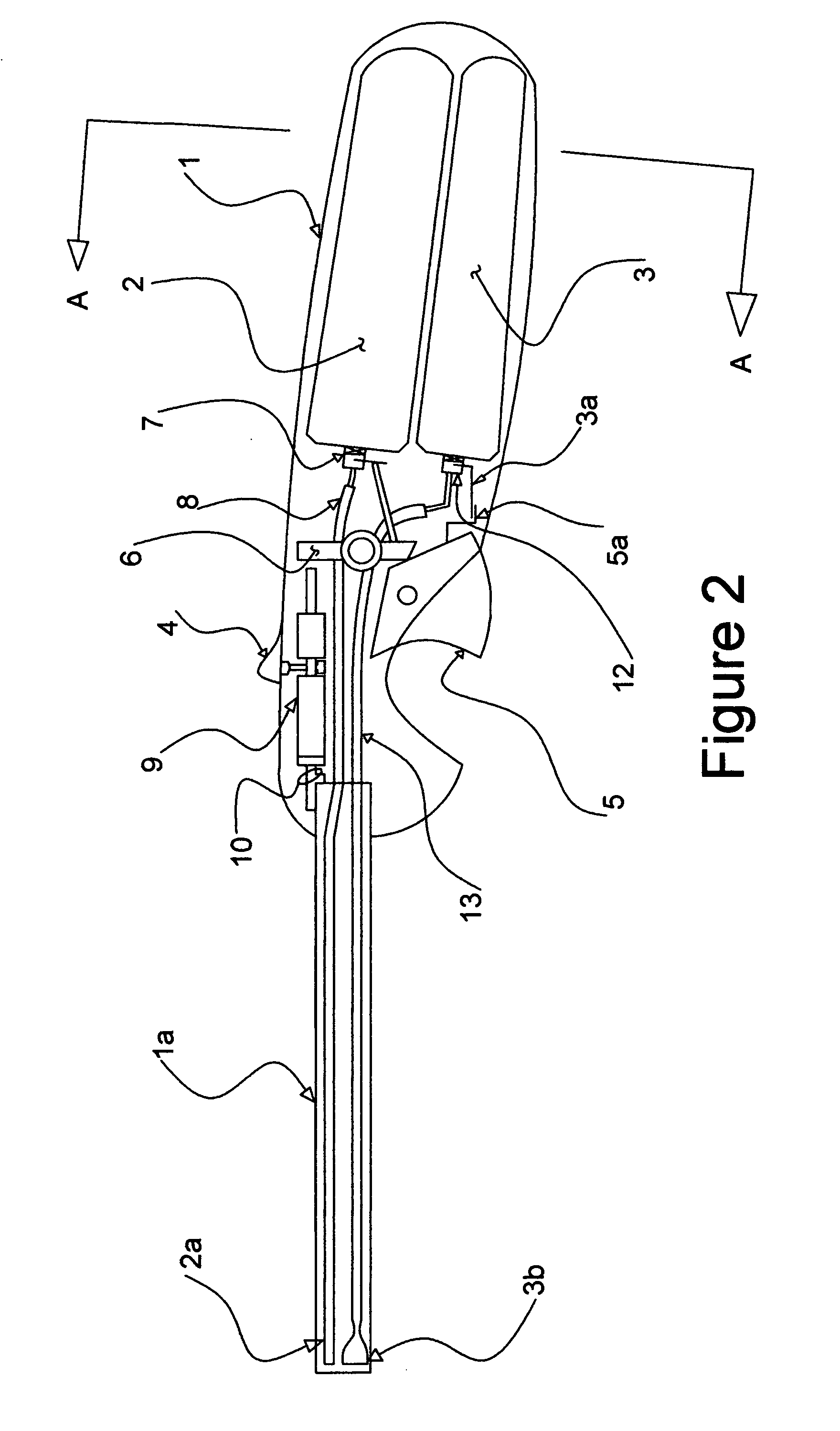
[0032] There exists a myriad configurations of “child proofing” and “triggering” schemes in utility lighters. Many involve pressing, twisting, squeezing and other manipulations to allow the lighter to light. What is shown is this embodiment is a simple “example” and not intended to be the invention. Also, the physical relationship between the components as depicted is not necessarily the only relationship but is represented as one of many typical ways the instant invention can be incorporated.

[0033]FIG. 1 describes the internal components of a typical utility lighter with the instant invention included. The shell housing 1 provides a grip and a platform for the components. In the handle 1 is various vessels one of which is a low pressure vessel 2 containing a flammable gas. The other vessel which part of the object of the present invention is a low pressure vessel 3 containing a flame extinguishing gas. Housing 1 is attached to a tubular extension 1a which house the capillary tubes...


PUM


Abstract

A single inexpensive device that creates flame utilizing an igniter that ignites an internal fuel source and a means and methods for extinguishing a flame all integrated into the same said device.

Description

CROSS REFERENCE TO RELATED APPLICATIONS [0001] This application claims the benefit of U.S. Provisional Application No. US60 / 740,716, filed on Nov. 30, 2005, the entire contents which are hereby incorporated by reference as if presented herein in their entirety.BACKGROUND ART Field of Invention [0002] The present invention pertains to a flame extinguishing method as an integral part of a typical “utility” lighter. The instant invention also applies to “pocket” lighters. Said lighters are available commercially and worldwide and are manufactured by a plurality of companies. [0003] These said lighters are universally and basically constructed of the same block components. Firstly, a handle being a vessel or containing a vessel that is filled with flammable low pressure gas. Secondly, attached to said vessel is a valve, variable or fixed, that controls or releases said gas. Thirdly, as a safety precaution various, “child proof” schemes such as dual manipulation or trigger pressures have...

Claims


Application Information

Patent Timeline
IPC IPC(8): F23D11/36F23D5/02
CPCF23D14/28F23D14/38F23Q2/287F23Q25/00
Inventor BLOOMFIELD, JOHN W.
Owner BLOOMFIELD JOHN W
Why Eureka
Try Eureka