Catalyst layer for gas diffusion electrode, method for manufacturing the same, membrane electrode assembly, and fuel cell

a catalyst layer and gas diffusion electrode technology, applied in the direction of cell components, final product manufacturing, sustainable manufacturing/processing, etc., can solve the problems of catalyst layer similar problems and performance drop

Active Publication Date: 2015-04-09
KANAGAWA INST OF IND SCI & TECH
View PDF3 Cites 9 Cited by
  • Summary
  • Abstract
  • Description
  • Claims
  • Application Information

AI Technical Summary

Benefits of technology

[0009]FIG. 1 shows a schematic partially enlarged explanatory view of a cathode catalyst layer of a polymer electrolyte fuel cell including a catalyst layer that reduces oxygen in the cathode. As shown in FIG. 1, the reduction reaction of oxygen is carried out on platinum particles of, for example, 2 to 3 nm serving as cathode catalysts in the presence of electrons and protons. Carbon particles support metallic catalysts as nanoparticles to increase the surface area of the metallic catalysts. Carbon particles further serve as supports that disperse the metallic catalyst particles to prevent aggregation of the metallic catalyst particles. Carbon particles that serve as supports also carry out an electron conduction as shown in FIG. 1.
[0017]The present invention achieves great effects that it is possible to provide a catalyst layer for gas diffusion electrode that can be used without using carbon supports, a method for manufacturing the same, a membrane electrode assembly, and a fuel cell.

Problems solved by technology

In reality, there is a problem that the gas diffusion rate is lower than the reaction rate in a high current density region in the catalyst layer, which causes a decrease in the performance because gas diffusion is rate-determining step.
While described above is the problem in the electrodes used for polymer electrolyte fuel cells, the similar problem may occur in catalyst layers for gas diffusion electrodes including other fuel cells as well.

Method used


Image

  • Catalyst layer for gas diffusion electrode, method for manufacturing the same, membrane electrode assembly, and fuel cell
  • Catalyst layer for gas diffusion electrode, method for manufacturing the same, membrane electrode assembly, and fuel cell
  • Catalyst layer for gas diffusion electrode, method for manufacturing the same, membrane electrode assembly, and fuel cell

Examples


first embodiment

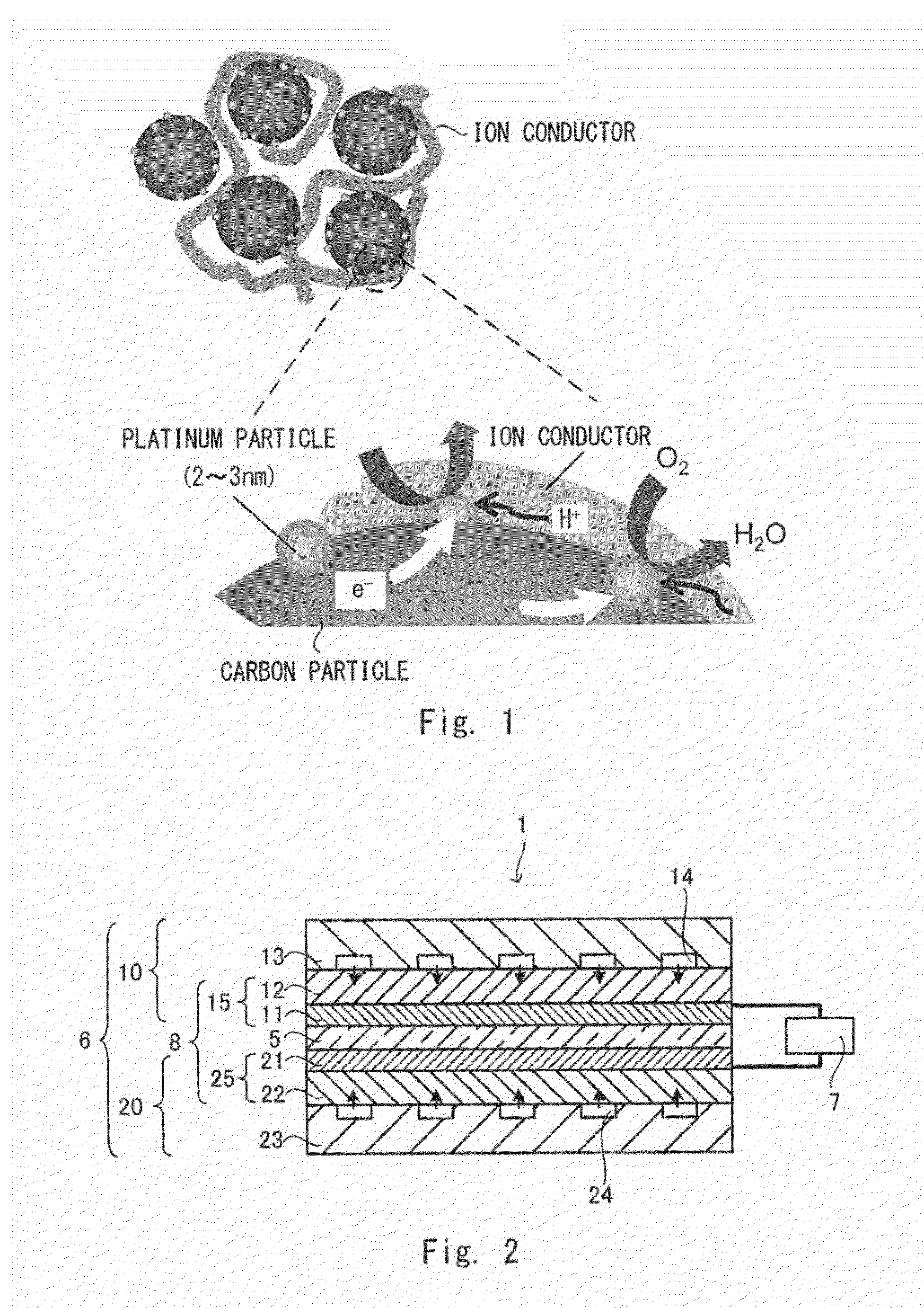
[0055]FIG. 2 is a schematic cross-sectional view showing one example of a substantial part of a polymer electrolyte fuel cell according to a first embodiment. A polymer electrolyte fuel cell 1 includes a cell 6 and an external circuit 7. The cell 6 includes a polymer electrolyte membrane S having ion conductivity, an anode unit 10 supplied with a fuel gas such as hydrogen, and a cathode unit 20 supplied with oxygen. Cells 6 are normally stacked according to the required output to form a battery.

[0056]The anode unit 10 includes an anode catalyst layer 11, a gas diffusion layer 12, and a separator 13 arranged in this order from the side of the polymer electrolyte membrane 5, and the cathode unit 20 includes a cathode catalyst layer 21, a gas diffusion layer 22, and a separator 23 arranged in this order from the side of the polymer electrolyte membrane 5. An electrode that can be concurrently contacted by gas, an electrolyte, and a catalyst layer is referred to as a gas diffusion elect...

second embodiment

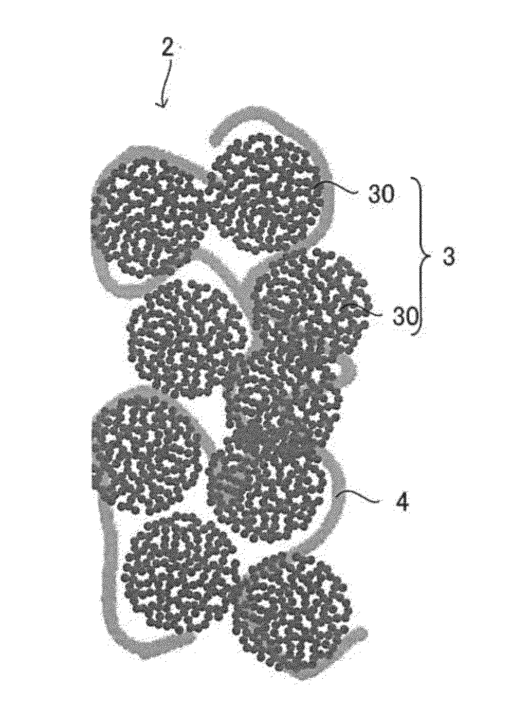
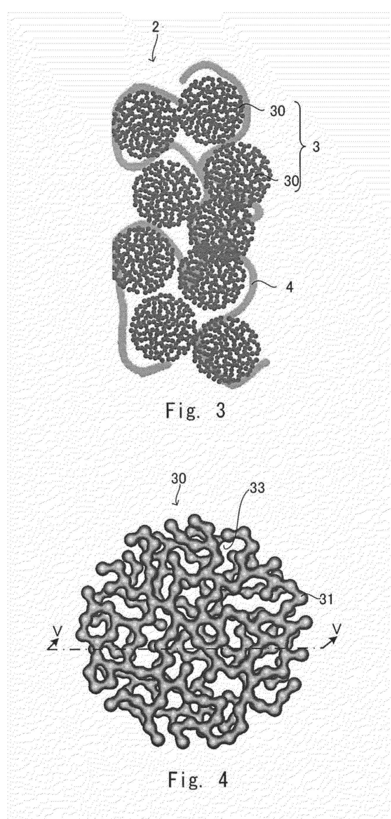
[0093]Next, one example of a catalyst layer for gas diffusion electrode different from that of the first embodiment will be described. The catalyst layer for gas diffusion electrode according to the second embodiment is different from the catalyst layer for gas diffusion electrode according to the first embodiment in that the ion conductor is provided mainly inside the capsule-like catalyst 30. However, the basic structures and the manufacturing method except for the following matters are similar to those of the first embodiment. In the following description, the components same as those in the first embodiment are denoted by the same reference symbols and the descriptions thereof will be omitted as appropriate.

[0094]FIG. 10 shows a partially enlarged schematic view of the catalyst layer for gas diffusion electrode according to the second embodiment. The catalyst layer for gas diffusion electrode 2 according to the second embodiment mainly includes the ion conductor 4 included in th...

third embodiment

[0102]A catalyst layer for gas diffusion electrode according to a third embodiment is different from those of the aforementioned embodiments that use the capsule-like catalysts 30 in that the network-like metallic catalyst 3 is formed of a rod-like catalyst. However, the basic configurations are the same as those of the second embodiment.

[0103]FIG. 11 shows a partially enlarged view schematically showing the catalyst layer for gas diffusion electrode 2 according to the third embodiment, and FIG. 12 shows a schematic view of the catalyst layers for gas diffusion electrode according to the third embodiment and an electrolyte membrane held therein. The catalyst, layer for gas diffusion electrode 2 includes, as shown in FIGS. 11 and 12, a rod-like catalyst 40 and an ion conductor 4.

[0104]The rod-like catalyst 40 forms, as shows in FIG. 11, a substantially tubular net-like skeleton structure 41, and the ion conductor 4 is arranged therein. The net-like skeleton structure 41 has a network...


PUM

PropertyMeasurementUnit
thicknessaaaaaaaaaa
thicknessaaaaaaaaaa
thicknessaaaaaaaaaa

Abstract

Provided is a catalyst layer for gas diffusion electrode that can be used without using carbon supports, a method for manufacturing the same, a membrane electrode assembly, and a fuel cell. The catalyst layer for gas diffusion electrode according to the present invention include a network-like metallic catalyst formed of a sintered body, the network-like metallic catalyst including nanoparticles linked with each other to have electron conductivity; and an ion conductor, at least a part of the ion conductor contacting the network-like metallic catalyst. Further, the membrane electrode assembly according to the present invention includes a polymer electrolyte membrane provided between an anode catalyst layer and cathode catalyst layer, and the catalyst layer for gas diffusion electrode stated above is used in at least one of the anode catalyst layer and the cathode catalyst layer.

Description

INCORPORATION BY REFERENCE[0001]This application is based upon and claims the benefit of priority from Japanese patent application No. 2013-209480, filed on Oct. 4, 2013 and Japanese patent application No. 2014-190596, filed on Sep. 18, 2014, the disclosure of which is incorporated herein in its entirety by reference.BACKGROUND OF THE INVENTION[0002]1. Field of the Invention[0003]The present invention relates to a fuel cell which generates electrical power by use of an electrochemical reaction. The present invention further relates to a membrane electrode assembly, a catalyst layer for gas diffusion electrode and a method for manufacturing the same, preferably applied to a fuel cell or the like.[0004]2. Description of Related Art[0005]A fuel cell is a generator having a structure including a pair of electrodes between which an electrolyte is interposed, one electrode being supplied with fuel and the other electrode being supplied with oxidant, thereby converting chemical energy into...

Claims


Application Information

Patent Timeline
Patent Type & Authority Applications(United States)
IPC IPC(8): H01M4/92H01M8/10H01M4/88H01M4/86
CPCH01M4/928H01M4/8657H01M8/1004H01M4/8663H01M4/8621H01M4/921H01M2300/0082H01M4/8892H01M2008/1095H01M2250/10H01M2250/20H01M2250/30H01M4/8875H01M4/9041H01M4/9091Y02E60/50Y02P70/50
Inventor YAMAGUCHI, TAKEOOGURA, SHUNTAMAKI, TAKANORIFUCHIGAMI, TERUAKIKITAMOTO, YOSHITAKAKUROKI, HIDENORI
Owner KANAGAWA INST OF IND SCI & TECH
Why Eureka
Try Eureka