Fuel injection control system ensuring steady balance in pressure in accumulator

a control system and fuel injection technology, applied in the direction of electric control, fuel injection apparatus, charge feed system, etc., can solve the problems of reducing the controllability of the pressure increasing the variation in the pressure of the fuel in the common rail, and unbalance between the amount of fuel flowing into and out of the common rail, so as to ensure the controllability of the pressure of the fuel in the accumulator

Active Publication Date: 2007-06-07
DENSO CORP
View PDF11 Cites 35 Cited by
  • Summary
  • Abstract
  • Description
  • Claims
  • Application Information

AI Technical Summary

Benefits of technology

[0011] According to one aspect of the invention, there is provided a fuel injection control system which may be employed for automotive common rail diesel engines. The fuel injection control system comprises: (a) a fuel pump works to feed fuel; (b) an accumulator in which the fuel fed from the fuel pump is to be accumulated at a given pressure; (c) fuel injectors each of which works to inject the fuel supplied from the accumulator into one of cylinders of a multi-cylinder internal combustion engine; (d) a fuel pressure sensor working to measure a pressure of the fuel in the accumulator; and (e) a controller working to energize the fuel injectors to inject the fuel at a sequence of given injection timings into the cylinders of the engine and also to control an operation of the fuel pump to feed an amount of the fuel to the accumulator at a sequence of controlled times for compensating for an amount of the fuel which flows out of the accumulator to bring the pressure of the fuel in the accumulator, as measured by the fuel pressure sensor, into agreement with a target value under feedback control. The controller is designed to perform a diagnosis function to diagnose whether at least one of the fuel injector has failed in operation or not. When it is determined that at least one of the fuel injectors has failed in operation, the controller alters a mode of the feedback control to decrease the amount of fuel fed from the fuel pump to the accumulator at one of the sequence of the controlled times which is at a selected interval away from one of the sequence of the injection timings at which the at least one of the fuel injectors is to be energized to inject the fuel into the engine, thereby avoiding feeding of an excessive amount of fuel to the accumulator near the time when the fuel injector determined to have failed in operation is to be energized to ensure a steady balance between the amounts of fuel flowing into and out of the accumulator to keep a variation in pressure in the accumulator within an allowable range. This also ensures the controllability of the pressure of the fuel in the accumulator.

Problems solved by technology

If, however, a failure has occurred in energizing one(s) of fuel injectors due to, for example, a disconnection of an injector's power supply line or one(s) of the fuel injectors encounters mechanical or electrical trouble in itself, it will result in instability in synchronization of the feeding of fuel to the common rail with the injection of fuel into the engine, thus leading to an unbalance between the amounts of fuel flowing into and out of the common rail.
This results in an increased variation in pressure of the fuel in the common rail and lowered controllability of the pressure in the common rail.

Method used


Image

  • Fuel injection control system ensuring steady balance in pressure in accumulator
  • Fuel injection control system ensuring steady balance in pressure in accumulator
  • Fuel injection control system ensuring steady balance in pressure in accumulator

Examples


first embodiment

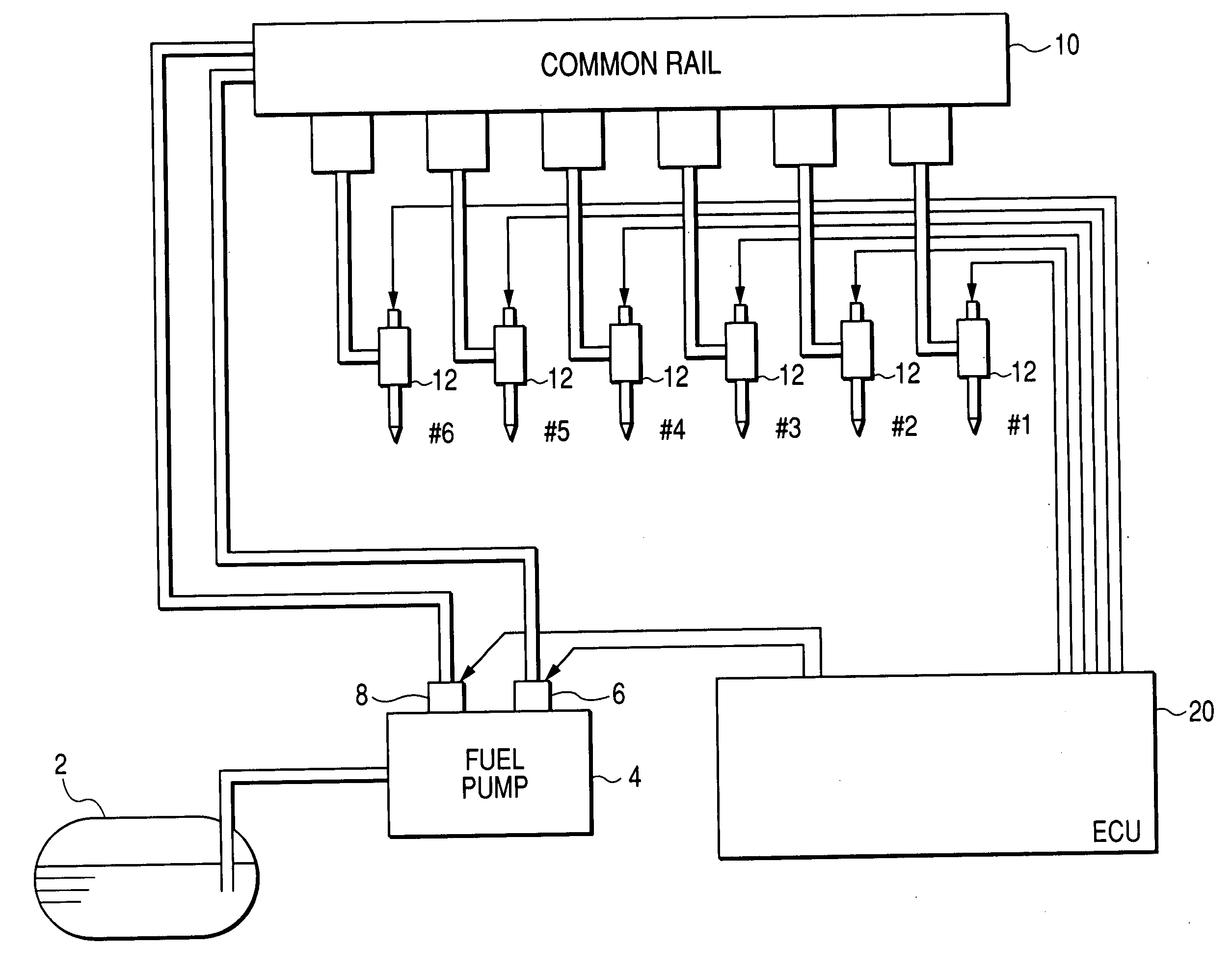
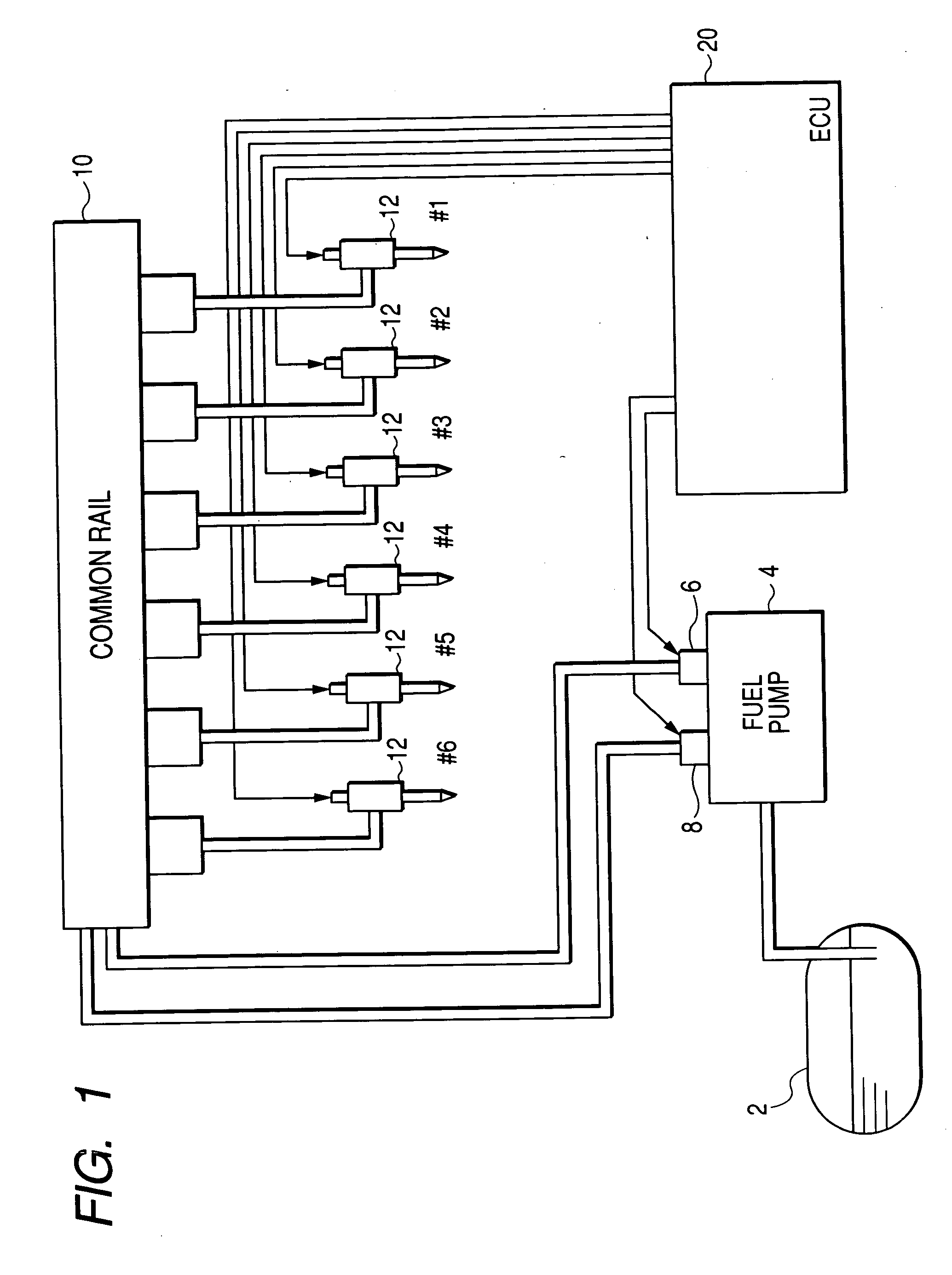
[0087] Referring to the drawings, wherein like reference numbers refer to like parts in several views, particularly to FIG. 1, there is shown an engine control system according to the invention which is designed, as an example, as a common rail injection system (also called an accumulator injection system) working to control injection of fuel into a diesel engine.

[0088] A fuel pump 4 works to pump fuel out of a fuel tank 2 and supply it to a common rail 10. The fuel pump 4 is equipped with a first and a second plunger (not shown) and a first and a second metering valve 6 and 8. Each of the first and second metering valves 6 and 8 is designed as a discharge control valve (also called a pump control valve) to control the amount of fuel sucked from the fuel tank 4 to be discharged to the common rail 10. Specifically, each of the first and second metering valves 6 and 8 is controlled by an electronic control unit (ECU) 20 to be opened during an interval in which a corresponding one of t...

second embodiment

[0111] The engine control system of the second embodiment will be described below which is designed to reduce the amount of fuel to a preselected value which is to be outputted from the first discharge control valve 6 or the second discharge control valve 8 which is associated with one of the first and second groups of the fuel injectors 12 determined by the microcomputer 21 to have failed to be opened.

[0112] FIGS. 8(a) to 8(g) demonstrates an example where the pressure in the common rail 10 is controlled in the fail-safe mode of the microcomputer 21 of the second embodiment. FIGS. 8(a) to 8(g) represent the same as in FIGS. 4(a) to 4(g).

[0113] In the illustrated example, a failure in energizing the fuel injector(s) 12 has occurred in the first group. The microcomputer 21 works to regulate the amount of fuel to be discharged from the first discharge control valve 6 to a value which is selected to be equivalent to a portion of the quantity of fuel flowing out of the common rail 10 e...

third embodiment

[0116] The engine control system of the third embodiment will be described below which is designed to perform a fail-safe program, as illustrated in FIG. 9, in a cycle.

[0117] After entering the program, the routine proceeds to step 30 wherein the fuel injectors 12 are diagnosed to monitor a failure in operation thereof in the same manner as described in FIG. 6. The routine proceeds to step 32 wherein it is determined whether a failure in energizing the fuel injector(s) 12 has occurred in the first group or not. If a YES answer is obtained meaning that any of the first group of the fuel injectors 12 has failed to be energized, then the routine proceeds to step 36 wherein a target amount of fuel to be discharged by the first discharge control valve 6 is determined based on the speed of the engine, the pressure of fuel in the common rail 10, and the temperature of the fuel in the common rail 10, as measured by the fuel pressure sensor 32, the crank angle sensor 34, and the fuel tempera...


PUM


Abstract

An accumulator fuel injection system working to energize fuel injectors to inject fuel at a sequence of injection timings into an internal combustion engine and also to control a fuel pump to feed the fuel to an accumulator at a sequence of controlled times for compensating for the amount of the fuel flowing out of the accumulator under feedback control. When having found a failure in operation of at least one of the fuel injectors, the system alters a mode of the feedback control to decrease the amount of fuel fed to the accumulator at one of the sequence of the controlled times which is at a selected interval away from one of the sequence of the injection timings at which the at least one of the fuel injectors is to be energized, thereby ensuring a steady balance between the amounts of fuel flowing into and out of the accumulator.

Description

CROSS REFERENCE TO RELATED DOCUMENT [0001] The present application claims the benefits of Japanese Patent Application No. 2005-350708 filed on Dec. 5, 2005, the disclosure of which is incorporated herein by reference. BACKGROUND OF THE INVENTION [0002] 1. Technical Field of the Invention [0003] The present invention relates generally to a fuel injection control system equipped with a fuel accumulator and a fuel injector working to inject fuel supplied from the fuel accumulator, and more particularly to such a system designed to ensure the steady balance between amounts of fuel fed to and discharged from the accumulator. [0004] 2. Background Art [0005] There are known common rail fuel injection systems for diesel engines of automotive vehicles which are equipped with a controller, a common rail, and a fuel pump. For example, Japanese Patent First Publication No. 62-258160 discloses a typical common rail injection system. The common rail injection system is typically designed to deter...

Claims


Application Information

Patent Timeline
Patent Type & Authority Applications(United States)
IPC IPC(8): F02M57/02F02M51/00F02M63/00
CPCF02D41/221F02D41/3845F02M59/462F02M63/0225
Inventor HAYAKAWA, YOSHIKI
Owner DENSO CORP
Why Eureka
Try Eureka