
Printed radio frequency identification (RFID) tag using tags-talk-first (TTF) protocol

a radio frequency identification and tag technology, applied in the field of electronic article surveillance, can solve the problems of high cost, prohibitively expensive for many anticipated applications, and the rtf approach is generally more complex in both interrogator and label design, so as to achieve reliable and simplified

Inactive Publication Date: 2007-06-07
ENSURGE MICROPOWER ASA
View PDF35 Cites 41 Cited by
  • Summary
  • Abstract
  • Description
  • Claims
  • Application Information

AI Technical Summary

Benefits of technology

[0014] Embodiments of the present invention can advantageously provide a reliable and simplified approach for multi-tag read capable EAS, HF, UHF and RFID systems using TTF anti-collision schemes. Further, embodiments of the present invention can advantageously be implemented using printing technology. These and other advantages of the present invention will become readily apparent from the detailed description of preferred embodiments below.

Problems solved by technology

An RTF approach is generally more complex in both interrogator and label designs (e.g., the number of transistors in the label circuit).
As a result, a drawback of this approach is its relatively high cost, making it prohibitively expensive for many anticipated applications.
Because of a general processing aim to decrease variation across wafers, such conventional photolithographic techniques may actually result in insufficient variation for message interval circuitry design in multi-tag read applications.
However, such a pseudo-random number generator circuit may be relatively complex for a label design, resulting in costs that are too high for use in many anticipated EAS and / or RFID system applications.

Method used


Image

  • Printed radio frequency identification (RFID) tag using tags-talk-first (TTF) protocol
  • Printed radio frequency identification (RFID) tag using tags-talk-first (TTF) protocol
  • Printed radio frequency identification (RFID) tag using tags-talk-first (TTF) protocol

Examples


Embodiment Construction

[0023] Reference will now be made in detail to the preferred embodiments of the invention, examples of which are illustrated in the accompanying drawings. While the invention will be described in conjunction with the preferred embodiments, it will be understood that they are not intended to limit the invention to these embodiments. On the contrary, the invention is intended to cover alternatives, modifications and equivalents that may be included within the spirit and scope of the invention as defined by the appended claims. Furthermore, in the following detailed description of the present invention, numerous specific details are set forth in order to provide a thorough understanding of the present invention. However, it will be readily apparent to one skilled in the art that the present invention may be practiced without these specific details. In other instances, well-known methods, procedures, components, and circuits have not been described in detail so as not to unnecessarily o...


PUM


Abstract

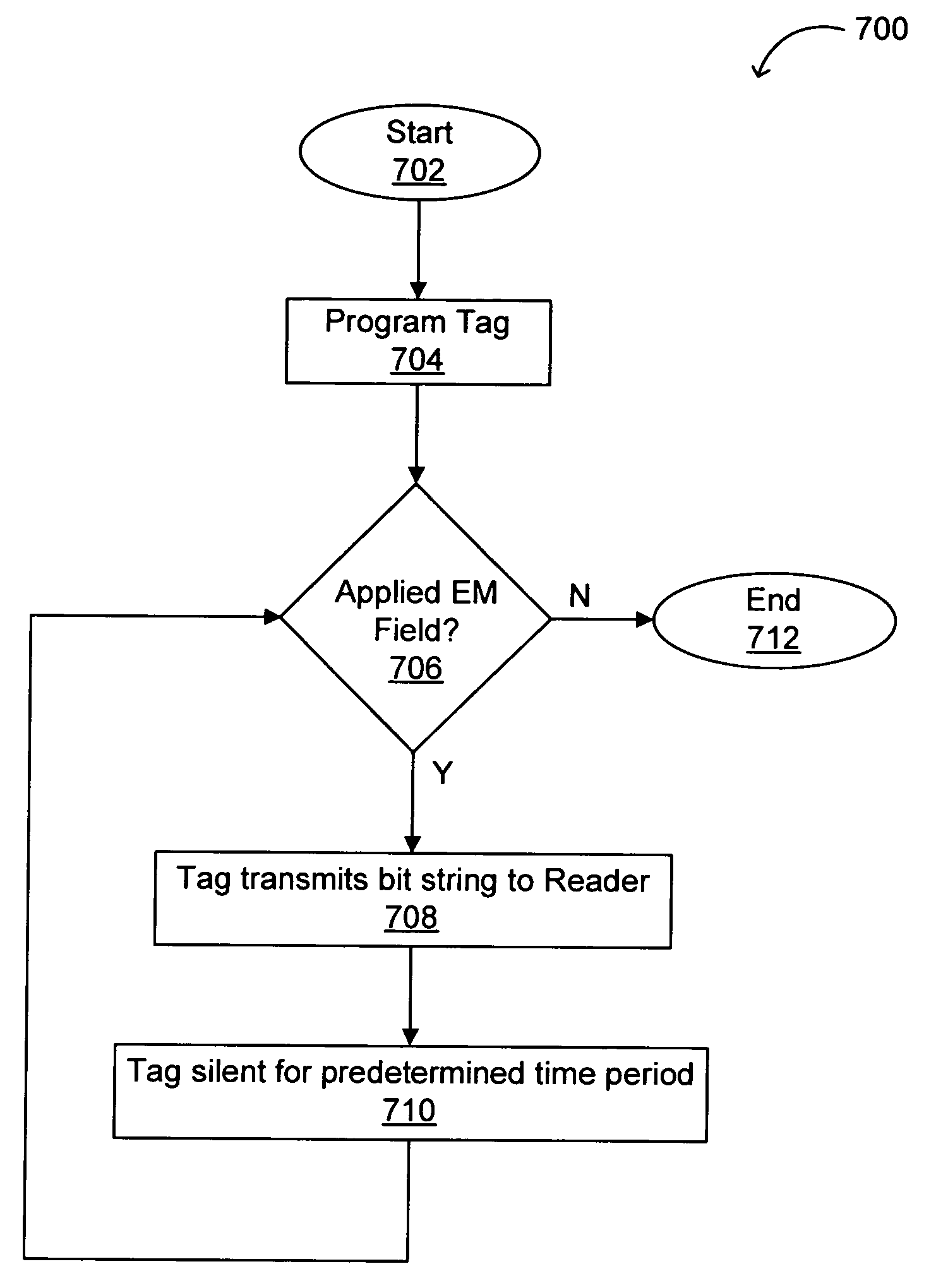
A method, algorithm, architecture, circuits, and / or systems for EAS, HF, UHF, and RFID designs suitable for multi-tag read applications using TTF anti-collision schemes are disclosed. In one embodiment, a tag for wirelessly communicating with a reader can include: (i) a memory portion with an identifier, the memory having at least one printed layer; and (ii) a circuit for providing a bit string followed by a predetermined silent period, where the bit string is related to the identifier. The tag can include pre-programmed memory bits (e.g., bits the value of which is programmed by printing), or alternatively, memory bits formed by conventional photolithography, but having connections made using printing technology to form the identifier, for example. A unique identifier for each tag or device used in a system under a given set of operating conditions can allow a reader to distinguish between them based on a length and / or value of a bit string, for example. Embodiments of the present invention can advantageously provide a reliable and simplified approach for multi-tag read capable EAS, HF, UHF, and RFID systems using TTF anti-collision schemes.

Description

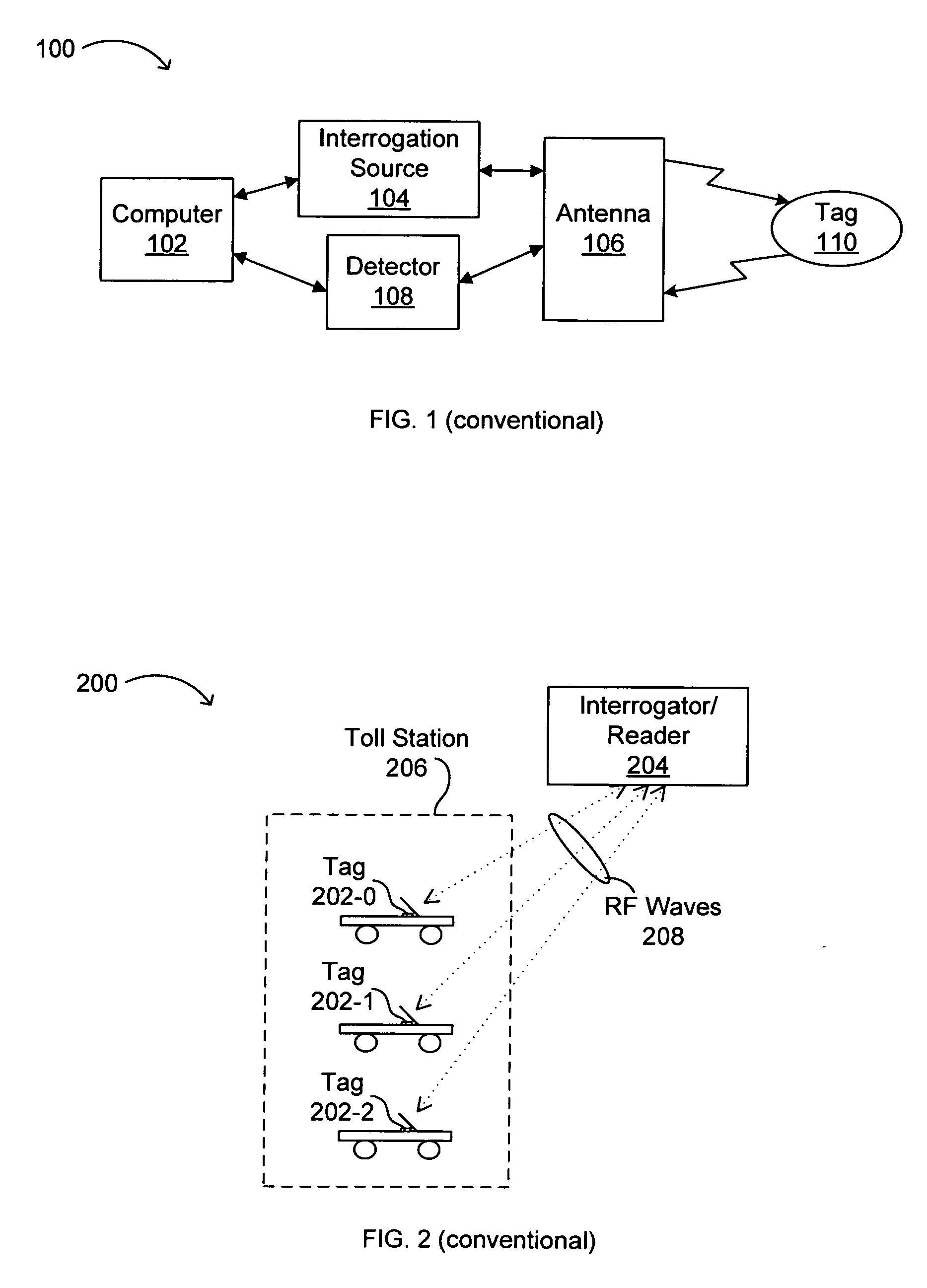
RELATED APPLICATIONS [0001] This application claims the benefit of U.S. Provisional Application No. 60 / 748,973, filed Dec. 7, 2005 (Attorney Docket No. IDR0641), which is incorporated herein by reference in its entirety.FIELD OF THE INVENTION [0002] The present invention generally relates to the field of electronic article surveillance (EAS), high frequency (HF), ultrahigh frequency (UHF), radio frequency (RF) and / or RF identification (RFID) tags and devices. More specifically, embodiments of the present invention pertain to EAS, HF, UHF, RF and / or RFID structures and methods of manufacture and / or production. DISCUSSION OF THE BACKGROUND [0003] Low cost RFID systems, typically including an interrogator or “reader” and an electronic label or “tag,” are desirable in a variety of applications, such as retail, supply chain management, logistics, library management, and baggage claim systems, as just a few examples. Other emerging applications include vehicle toll tracking and / or managem...

Claims


Application Information

Patent Timeline
Patent Type & Authority Applications(United States)
IPC IPC(8): H04Q5/22
CPCG06K19/0723B82Y30/00G06K17/00G06K19/07G06K19/077
Inventor SUBRAMANIAN, VIVEKPAVATE, VIKRAM
Owner ENSURGE MICROPOWER ASA
Learn More