

Vehicle lamp
a technology for lamps and vehicles, applied in semiconductor devices for light sources, lighting and heating apparatus, transportation and packaging, etc., can solve the problem of insufficient degree of freedom of lamps and lenses
- Summary
- Abstract
- Description
- Claims
- Application Information
AI Technical Summary
Benefits of technology
Problems solved by technology
Method used
Image

Examples
embodiment 1
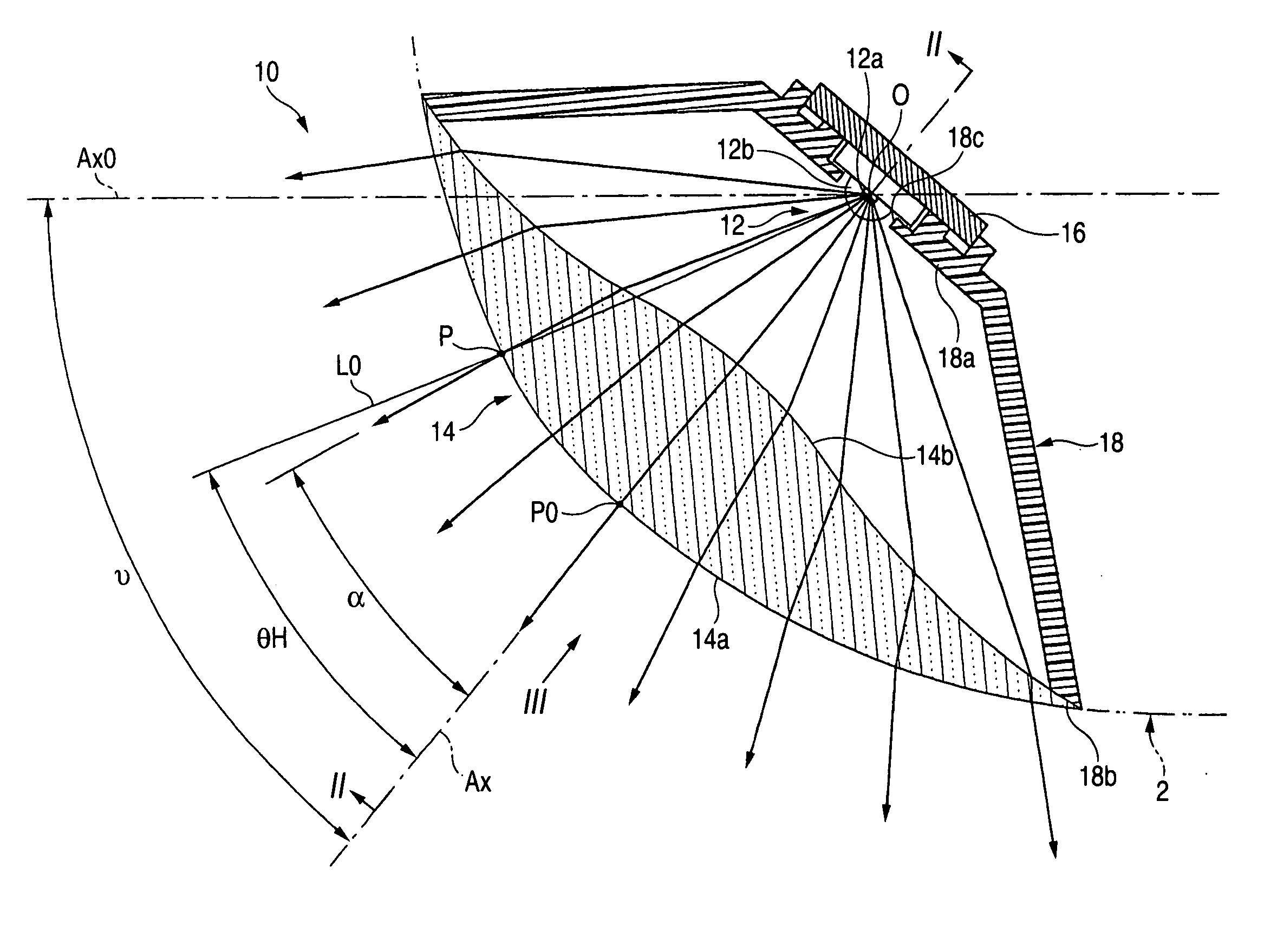
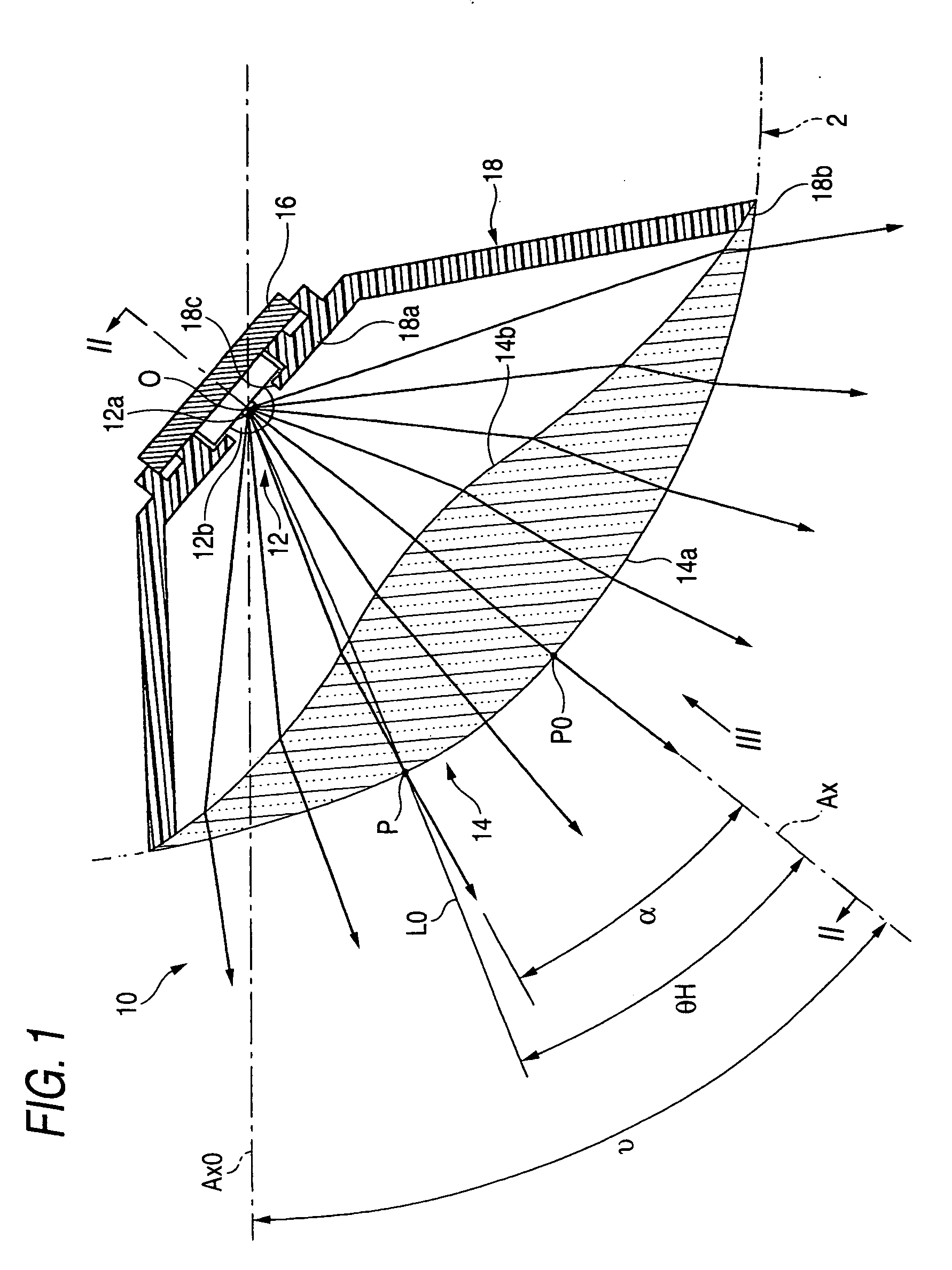
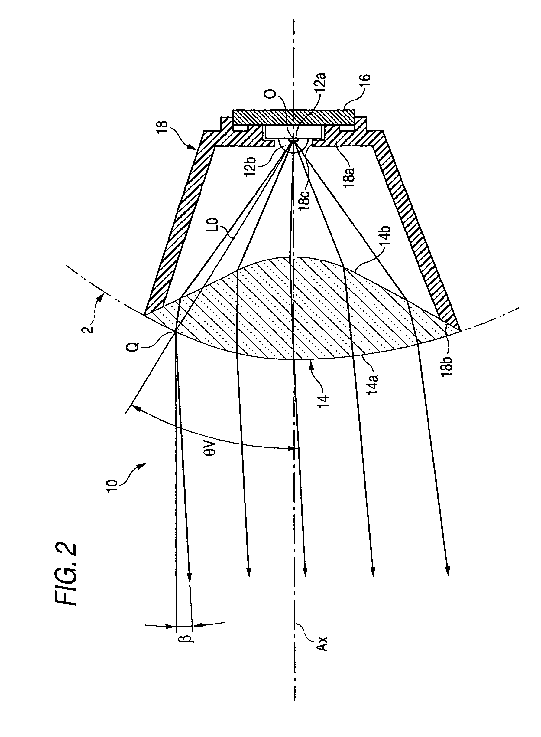
[0044]FIG. 1 is the plane sectional view showing the vehicle lamp 10 according to the first exemplary embodiment, FIG. 2 is the sectional view taken along the line II-II of FIG. 1, and FIG. 3 is the view seen in the direction of the arrow mark III in FIG. 1.
[0045] As shown in FIGS. 1 to 3, the vehicle lamp 10 according to the first exemplary embodiment is a cornering lamp mounted to a left front end corner portion of a vehicle body 2, which illuminates a road surface on a left skewed front side of a vehicle when the vehicle is turned to run to a left side.
[0046] The vehicle lamp 10 includes a light emitting diode 12 arranged on an optical axis Ax extended in a direction inclined to an axis line Ax0 extended in a front and rear direction of the vehicle to an outer side in a vehicle width direction by a predetermined angle ν (specifically, about ν=50°), and a lens 14 arranged on a front side of the light emitting diode 12 (that is, front side in optical axis Ax direction) for deflec...
embodiment 2
[0079]FIG. 7 is a front view showing the vehicle lamp 110 according to the second exemplary embodiment, FIG. 8 is a sectional view taken along the line VIII-VIII of FIG. 7, and FIG. 9 is a sectional view taken along the line IX-IX of FIG. 7.
[0080] As shown in FIGS. 7 to 9, the vehicle lamp 110 according to the second exemplary embodiment is a lamp unit integrated as a portion of a headlamp mounted to a left front end corner portion of a vehicle body to irradiate light for forming a high beam light distribution pattern. The headlamp includes a transparent cover 102 that is plain (does not deflect light) and extends flush with a surface of the vehicle body, and the vehicle lamp 110 is contained inside a lamp chamber constituted by the transparent cover 102 and a lamp body (which is not illustrated).
[0081] The vehicle lamp 110 is constituted by including a light source bulb 112 arranged on an optical axis Ax extended in a front and rear direction of a vehicle, a reflector 116 for ref...
embodiment 3
[0114]FIG. 13 is a plane sectional view showing a vehicle lamp 210 according to the third exemplary embodiment, FIG. 14 is a sectional view taken along the line XIV-XIV of FIG. 13, and FIG. 15 is a view seen in a direction of the arrow mark XV in FIG. 13.
[0115] As shown in FIGS. 13 to 15, although a basic constitution of the vehicle lamp 210 according to the third exemplary embodiment is similar to that in the case of the first exemplary embodiment, a constitution of the lens 214 partially differs from that of the case of the first exemplary embodiment.
[0116] That is, the lens 214 of the third exemplary embodiment is formed such that a center region 214a2 disposed at a vicinity of the optical axis Ax in a front side surface 214a thereof is displaced to a rear side from a general peripheral region 214a1 surrounding the center region 214a2.
[0117] More specifically, in the front side surface 244a of the lens 214, the general peripheral region 214a1 is constituted by a first freely f...
PUM
 Abstract
Description
Claims
Application Information