Glass package for optical device

a technology of optical devices and glass, applied in the field of optical networking technology, can solve problems such as complaints of standards by glass optical filters, and achieve the effects of reducing thermal expansion coefficient, significant performance advantages, and less cos

Active Publication Date: 2007-06-07
II VI DELAWARE INC
View PDF13 Cites 4 Cited by
  • Summary
  • Abstract
  • Description
  • Claims
  • Application Information

AI Technical Summary

Benefits of technology

[0023] The glass housing may be comprised of two glass pigtail tubes and a glass center piece tube that are secured by an epoxy that secures the three tubes together after curing. In one embodiment of the invention, the inner diameters of the pigtail tubes are smaller than the inner diameter of the center piece tube so that additional space is provided for alignment of pigtails to focusing lenses. Additionally, a glass tube package may be used to surround the secured tubes. In one embodiment, the glass housing protects and secures two D-lenses that operate as focusing lenses, a filter chip and filter holder. A first D-lens focuses an incident light signal on a WDM filter which passes a single or group of optical channels and reflects the remaining channels. A second D-lens focuses the filtered optical signal into a transmission port of an optical fiber pigtail. The first D-lens may focus any reflected channels into a reflective port in a corresponding fiber pigtail.
[0024] The glass optical filter offers significant performance advantages, compliance with RoHS and other standards, and is less expensive than its metallic counterparts. The glass optical filter has a relatively lower coefficient of thermal expansion and thus is less sensitive to temperature change. Additionally, the glass material comprising the pigtail and center piece tubes, and the epoxy material used to secure the tubes, does not contain metallic substances. Accordingly, the glass optical filter is complaint with standards relating to hazardous material.
[0025] The D-lenses also offer distinct advantages in their combination with the glass housing. In particular, the D-lens focus length allows for a relatively compact design of the glass optical filter. The D-lens also allows for different angles of a pigtail depending on whether a single or dual fiber pigtail is used.

Problems solved by technology

Accordingly, the glass optical filter is complaint with standards relating to hazardous material.

Method used


Image

  • Glass package for optical device
  • Glass package for optical device
  • Glass package for optical device

Examples


Embodiment Construction

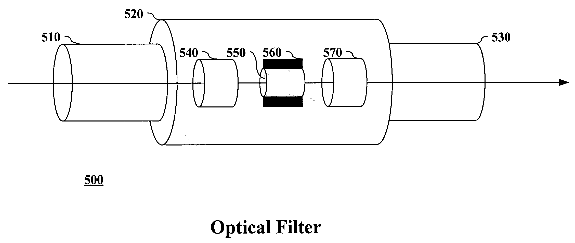
[0037] A glass optical filter is described that optically connects two optical fibers and may filter a single or group of channels from a WDM signal that is being communicated between the optical fibers. The glass optical filter may be comprised of two pigtail tubes having smaller interior diameters than a center piece tube that couples the two pigtail tubes together. In one embodiment of the invention, D-lenses are positioned within the glass optical filter and function as focusing lenses. The characteristics of the glass housing and D-lens provide a preferred environment for aligning optical fiber pigtails to the focusing lenses. In particular, a larger space between a D-lens and a pigtail is provided and a more dynamic angle allowance that allows for optimization of return loss and polarization dependent loss.

[0038] In the following description, for purpose of explanation, specific details are set forth in order to provide an understanding of the invention. It will be apparent, ...


PUM


Abstract

A glass optical filter is described that optically connects two optical fibers and may filter a single or group of channels from a WDM signal that is being communicated between the optical fibers. The glass optical filter may be comprised of two pigtail tubes having smaller interior diameters than a center piece tube that couples the two pigtail tubes together. In one embodiment of the invention, D-lenses are positioned within the glass optical filter and function as focusing lenses. The characteristics of the glass housing and D-lens provide a preferred environment for aligning optical fiber pigtails to the focusing lenses.

Description

BACKGROUND [0001] A. Technical Field [0002] The present invention relates generally to optical networking technology, and more particularly, to a glass package for optical devices, such as an optical filter. [0003] B. Background of the Invention [0004] The development of optical networking technologies has provided large amounts of network capacity on which data may be communicated. This increased capacity has facilitated the development of high bandwidth applications, including multimedia, voice and video applications, which require large amounts of data to be communicated between network clients. Furthermore, other bandwidth-hungry applications are continually being developed to take advantage of the capacity provided by optical networks. [0005] Wavelength division multiplexing technology, including dense wavelength division multiplexing and coarse wavelength multiplexing, is a significant technological advancement that has resulted in an increase of bandwidth in optical networks....

Claims


Application Information

Patent Timeline
Patent Type & Authority Applications(United States)
IPC IPC(8): G02B6/26G02B6/32
CPCG02B6/2937G02B6/29389G02B6/29398G02B6/32
Inventor JIN, XINGANGLAN, FAHUAZHANG, JUNFEILIN, KANG
Owner II VI DELAWARE INC
Why Eureka
Try Eureka