
CMC component and method of fabrication

Inactive Publication Date: 2007-06-07
SIEMENS ENERGY INC
View PDF15 Cites 24 Cited by
  • Summary
  • Abstract
  • Description
  • Claims
  • Application Information

AI Technical Summary

Problems solved by technology

Monolithic ceramic materials generally exhibit higher operating temperature limits than do metals, however they lack the toughness and tensile load carrying capabilities required for most structural applications.

Method used


Image

  • CMC component and method of fabrication
  • CMC component and method of fabrication
  • CMC component and method of fabrication

Examples


Embodiment Construction

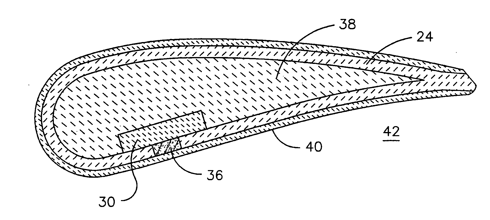
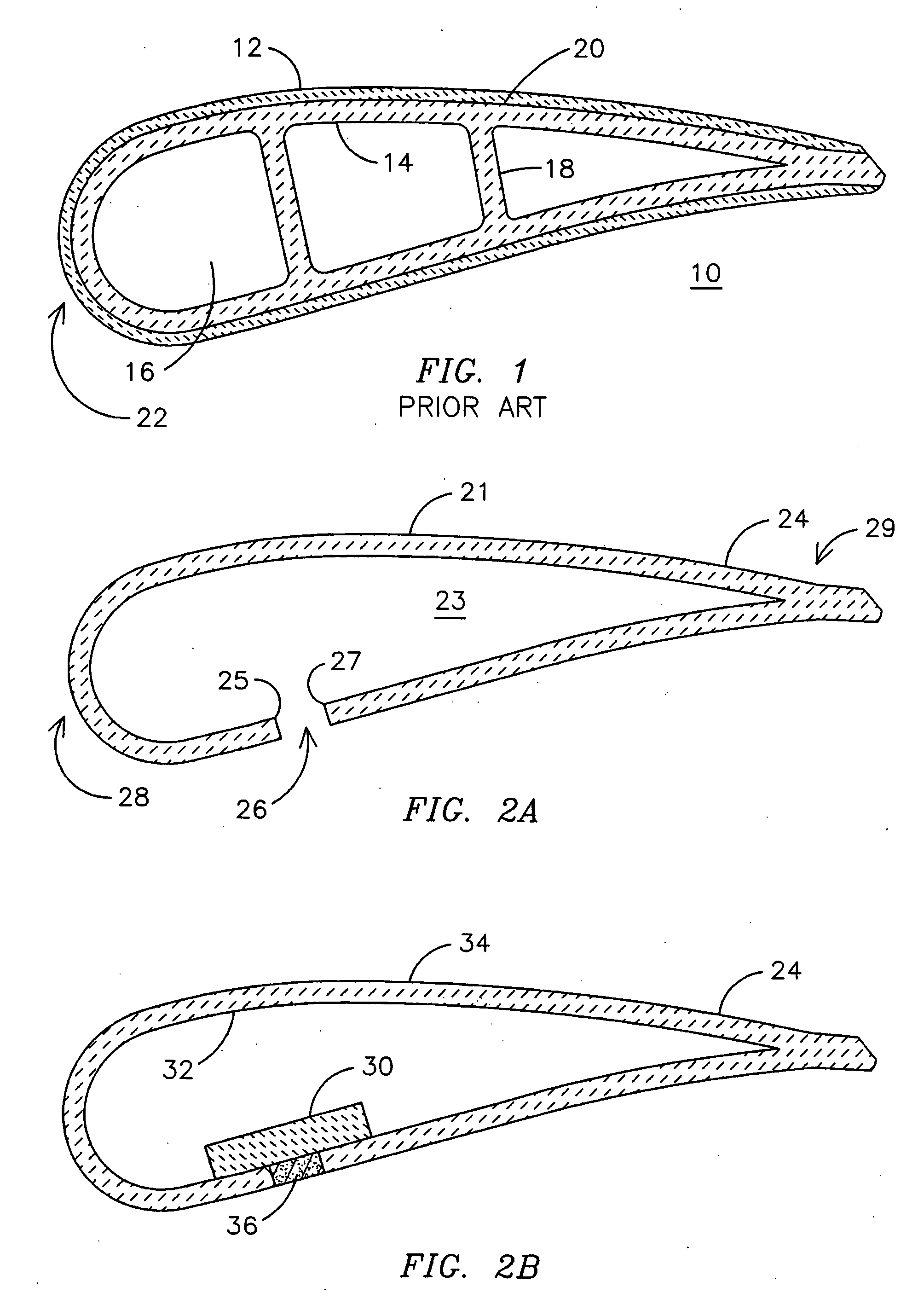
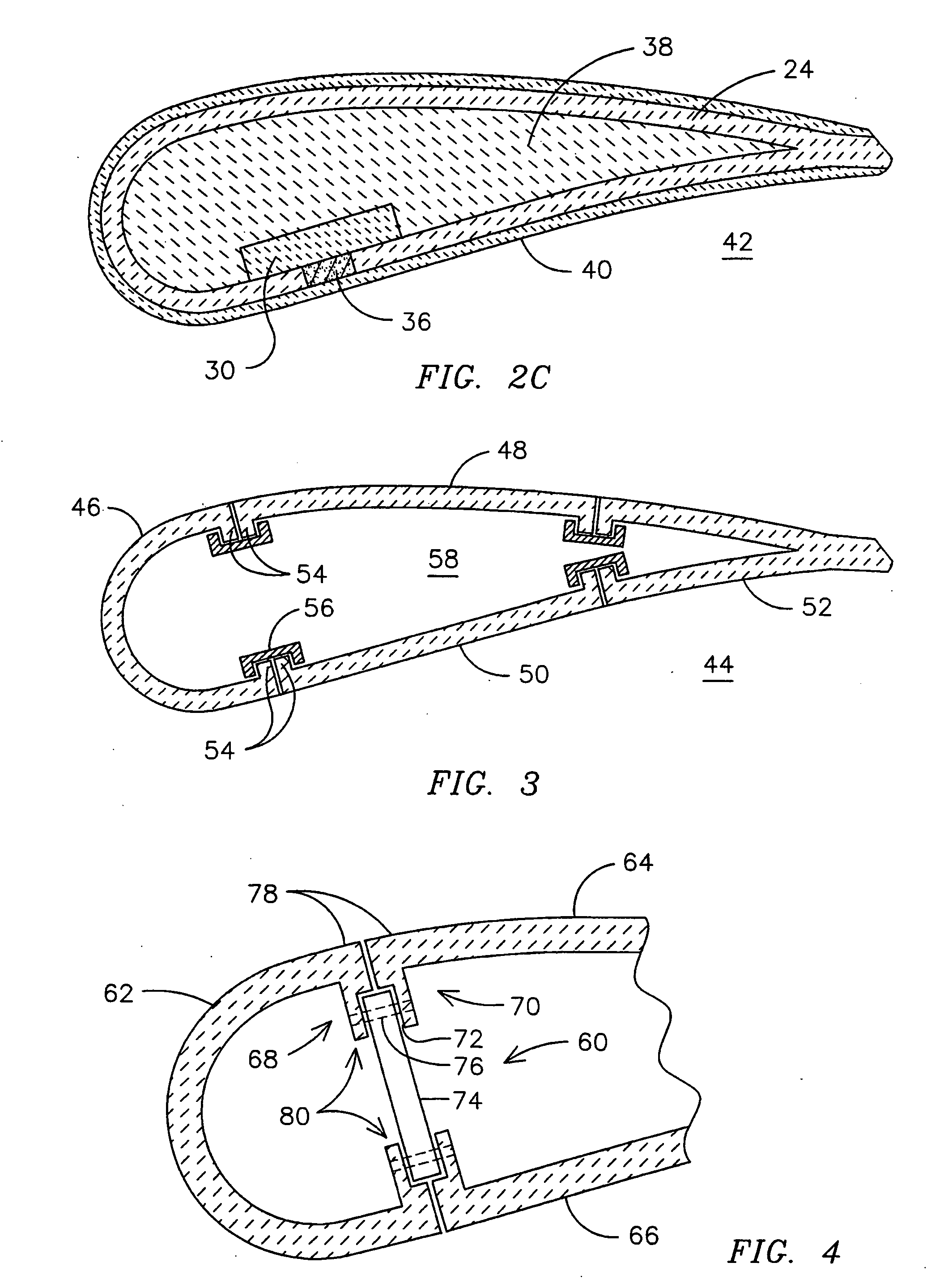
[0010] Interlaminar cracks are known to occur between plies of the CMC material used to form the leading edge portion 22 of structures such as shown in FIG. 1 during the fabrication of such structures. Interlaminar cracks are deleterious to the performance of the CMC airfoil 10 from a variety of perspectives. First, delamination across the thickness of the CMC structural member 14 results in a decrease in thermal conductivity, thereby reducing the effectiveness of the cooling air flowing through passages 16. Second, small interlaminar cracks formed during fabrication may be susceptible to crack propagation during operation due to the interlaminar stresses created by thermal gradients through the thickness of the CMC material. Third, delaminated CMC material will cause the vane 10 to become susceptible to vibration damage and spallation of the overlying insulating material 12. Fourth, delamination will result in a reduction in load-carrying capability of the CMC wall under bending lo...


PUM

PropertyMeasurementUnit
Shapeaaaaaaaaaa

Abstract

An airfoil (44) formed of a plurality of pre-fired structural CMC panels (46, 48, 50, 52). Each panel is formed to have an open shape having opposed ends (54) that are free to move during the drying, curing and / or firing of the CMC material in order to minimize interlaminar stresses caused by anisotropic sintering shrinkage. The panels are at least partially pre-shrunk prior to being joined together to form the desired structure, such as an airfoil (42) for a gas turbine engine. The panels may be joined together using a backing member (30), using flanged ends (54) and a clamp (56), and / or with a bond material (36), for example.

Description

FIELD OF THE INVENTION [0001] This invention relates generally to ceramic matrix composite (CMC) materials formed as structural members, and more specifically to CMC airfoil members as may be used in a gas turbine engine. BACKGROUND OF THE INVENTION [0002] Ceramic materials are often used in high temperature applications such as the hot combustion gas path components of a gas turbine engine. Monolithic ceramic materials generally exhibit higher operating temperature limits than do metals, however they lack the toughness and tensile load carrying capabilities required for most structural applications. Ceramic matrix composite (CMC) materials are known to provide a combination of high temperature capability, strength and toughness. [0003]FIG. 1 is a cross-sectional view of a prior art component, specifically a stationary airfoil or vane 10 for a gas turbine engine that is formed using ceramic materials. Vane 10 includes a layer of a very high temperature ceramic insulating material 12...

Claims


Application Information

Patent Timeline
IPC IPC(8): F03B3/12
CPCF01D5/147F01D5/282Y10T29/49337Y10T29/49339F01D5/284
Inventor MORRISON, JAY A.MERRILL, GARY B.VANCE, STEVEN JAMESALBRECHT, HARRY A.SHTEYMAN, YEVGENIY
Owner SIEMENS ENERGY INC
Learn More