System and method for control of fluid pressure

Active Publication Date: 2007-06-07
ENTEGRIS INC
View PDF99 Cites 112 Cited by
  • Summary
  • Abstract
  • Description
  • Claims
  • Application Information

AI Technical Summary

Benefits of technology

[0009] Embodiments of the present invention provide an advantage by lowering the maximum fluid pressure in a pump based, for example, on user programmable pressure thresholds.
[0010] Another adv

Problems solved by technology

Many photochemicals used in the semiconductor industry today are very expensive, frequently costing as much as $1000 a liter.
Current multiple stage pumps can cause sharp pressure spikes in the liquid.
Such pressure spikes and subsequent drops in pressure may be damaging to the

Method used


Image

  • System and method for control of fluid pressure
  • System and method for control of fluid pressure
  • System and method for control of fluid pressure

Examples


Embodiment Construction

[0025] Preferred embodiments of the present invention are illustrated in the FIGUREs, like numerals being used to refer to like and corresponding parts of the various drawings.

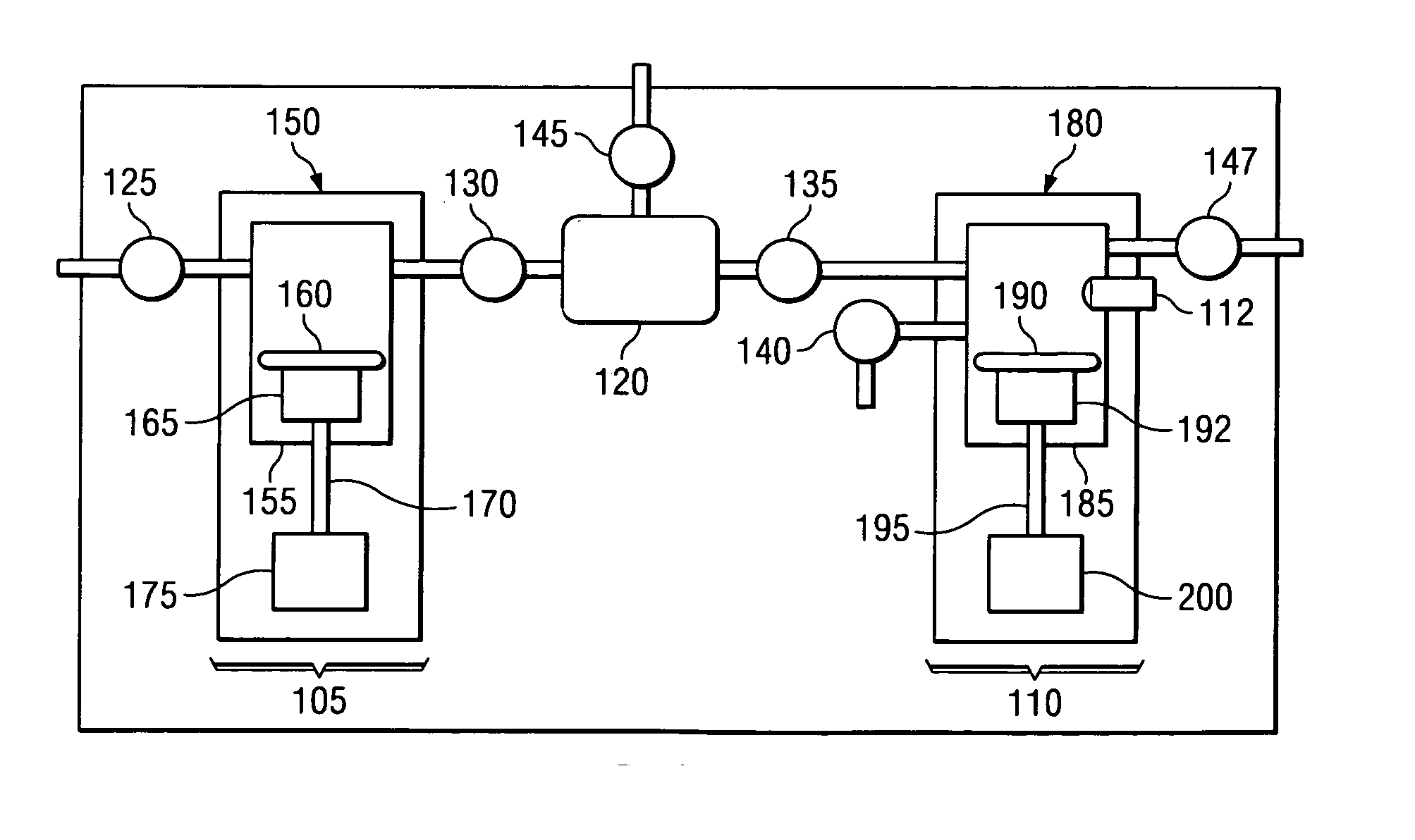
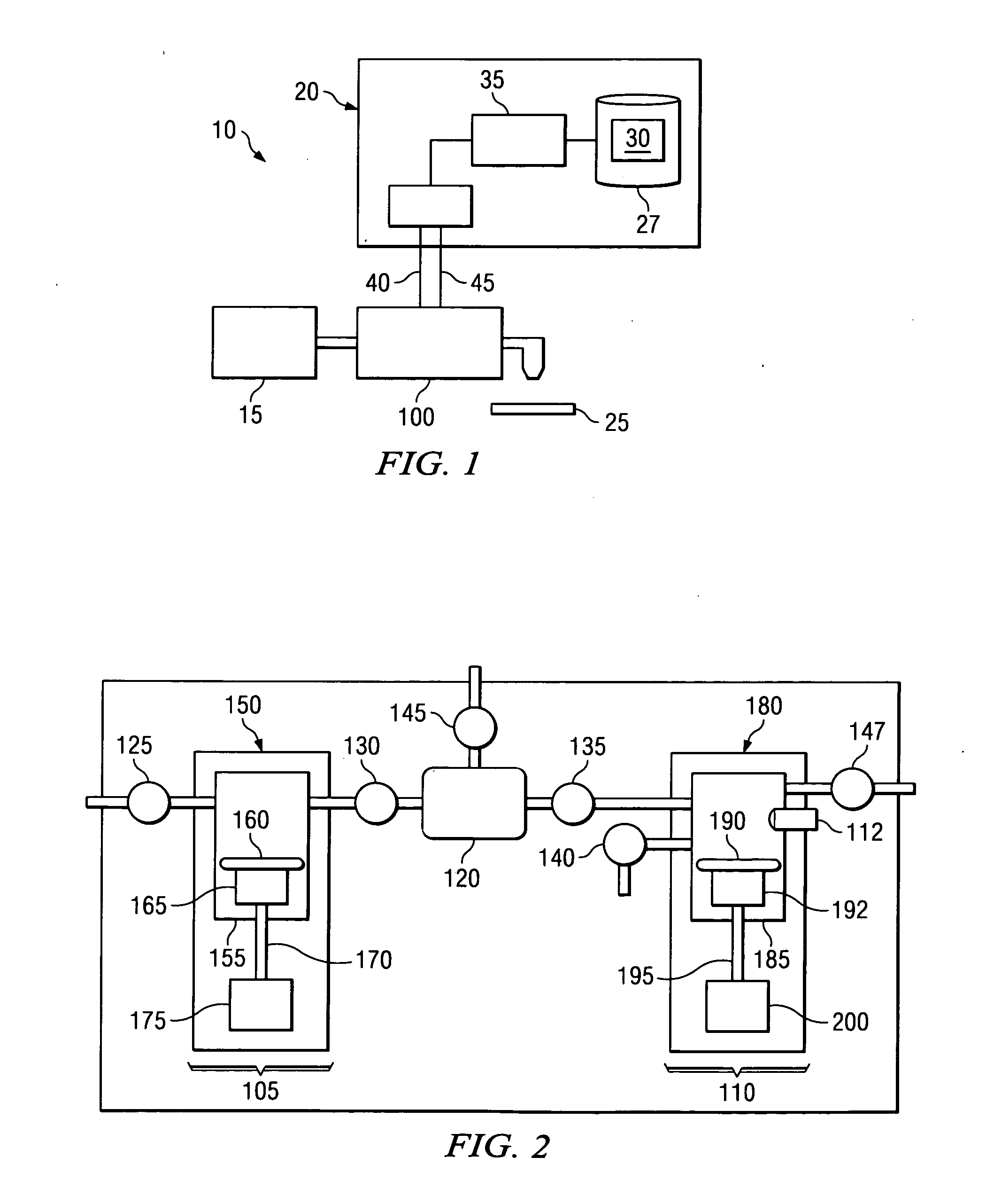
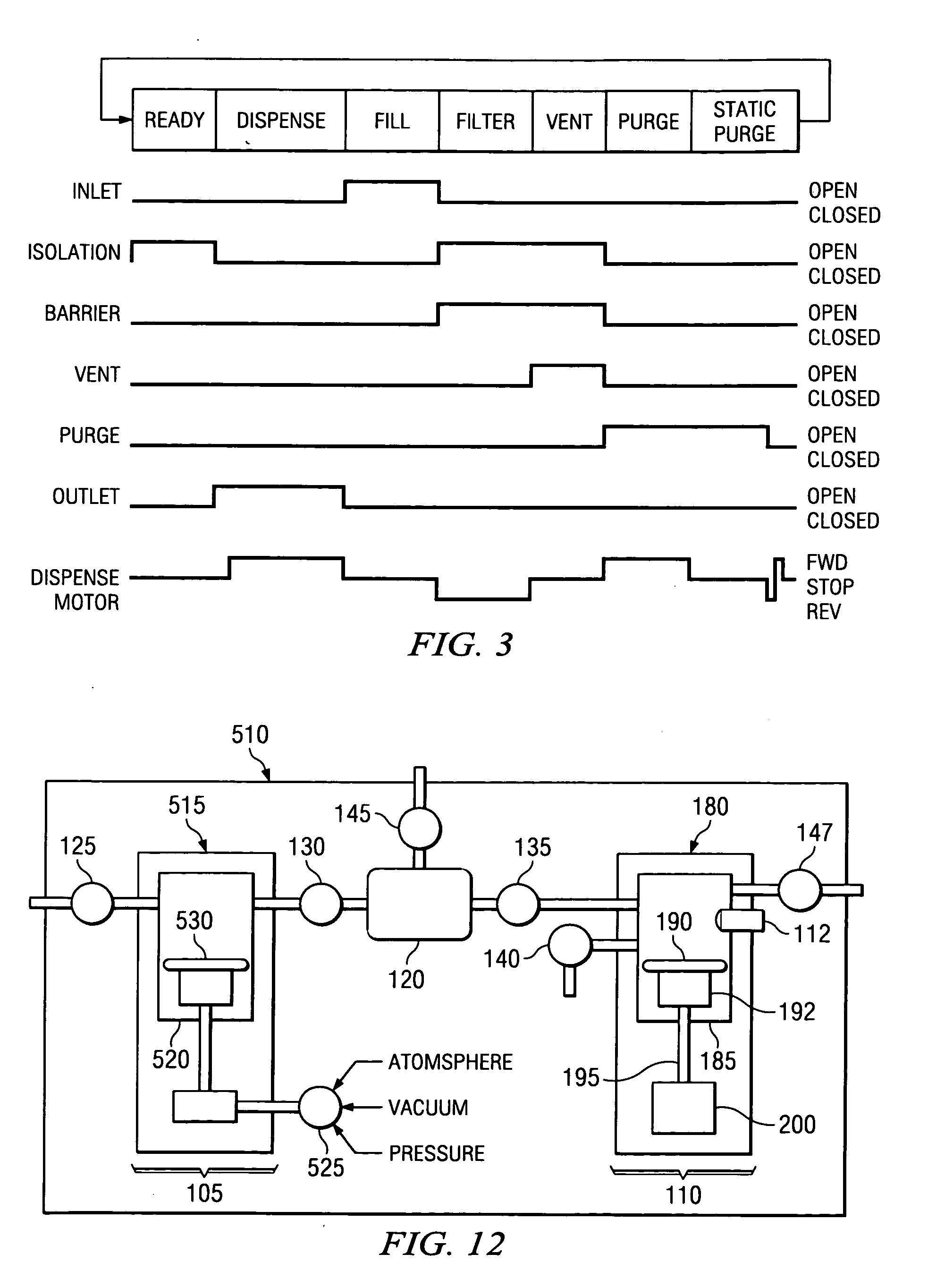
[0026] Embodiments of the present invention are related to a pumping system that accurately dispenses fluid using a multiple stage (“multi-stage”) pump. More particularly, embodiments of the present invention provide for control of a feed stage pump to regulate fluid pressure at a downstream dispense stage pump. According to one embodiment of the present invention, a pressure sensor at the dispense stage pump determines the pressure in a dispense chamber. When the pressure reaches a predefined threshold, the dispense stage pump can begin to increase the available volume of the dispense chamber (e.g. by moving a diaphragm) at a predefined rate, thereby causing the pressure in the dispense chamber to drop. If the pressure in the dispense chamber drops below a minimum threshold (or set point), the speed at which...


PUM


Abstract

Embodiments of the present invention are related to a pumping system that accurately dispenses fluid using a multiple stage (“multi-stage”) pump. More particularly, embodiments of the present invention provide for control of a feed stage pump to regulate fluid pressure at a downstream dispense stage pump. According to one embodiment of the present invention, a pressure sensor at the dispense stage pump determines the pressure in a dispense chamber. When the pressure reaches a predefined threshold, the dispense stage pump can begin to increase the available volume of the dispense chamber, thereby causing the pressure in the dispense chamber to drop. As the pressure decreases/increases at the downstream pump, the pressure applied by the upstream pump can bed increased/decreased.

Description

TECHNICAL FIELD OF THE INVENTION [0001] This invention relates generally fluid pumps. More particularly, embodiments of the present invention relate to multi-stage pumps. Even more particularly, embodiments of the present invention relate to controlling pressure in a multi-stage pump used in semiconductor manufacturing. BACKGROUND OF THE INVENTION [0002] There are many applications for which precise control over the amount and / or rate at which a fluid is dispensed by a pumping apparatus is necessary. In semiconductor processing, for example, it is important to control the amount and rate at which photochemicals, such as photoresist chemicals, are applied to a semiconductor wafer. The coatings applied to semiconductor wafers during processing typically require a flatness across the surface of the wafer that is measured in angstroms. The rates at which processing chemicals, such as photoresists chemicals, are applied to the wafer has to be controlled in order to ensure that the proces...

Claims


Application Information

Patent Timeline
IPC IPC(8): F04B41/06
CPCF04B1/08F04B23/04F04B23/06F04B41/06F04B43/088F04B2205/04F04B49/08F04B49/103F04B51/00F04B2203/0209F04B2205/03F04B49/065
Inventor GONNELLA, GEORGECEDRONE, JAMES
Owner ENTEGRIS INC
Why Eureka
Try Eureka