
Controlled needle-free eye injector

Inactive Publication Date: 2007-06-07
PFIZER INC +1
View PDF55 Cites 70 Cited by
  • Summary
  • Abstract
  • Description
  • Claims
  • Application Information

AI Technical Summary

Benefits of technology

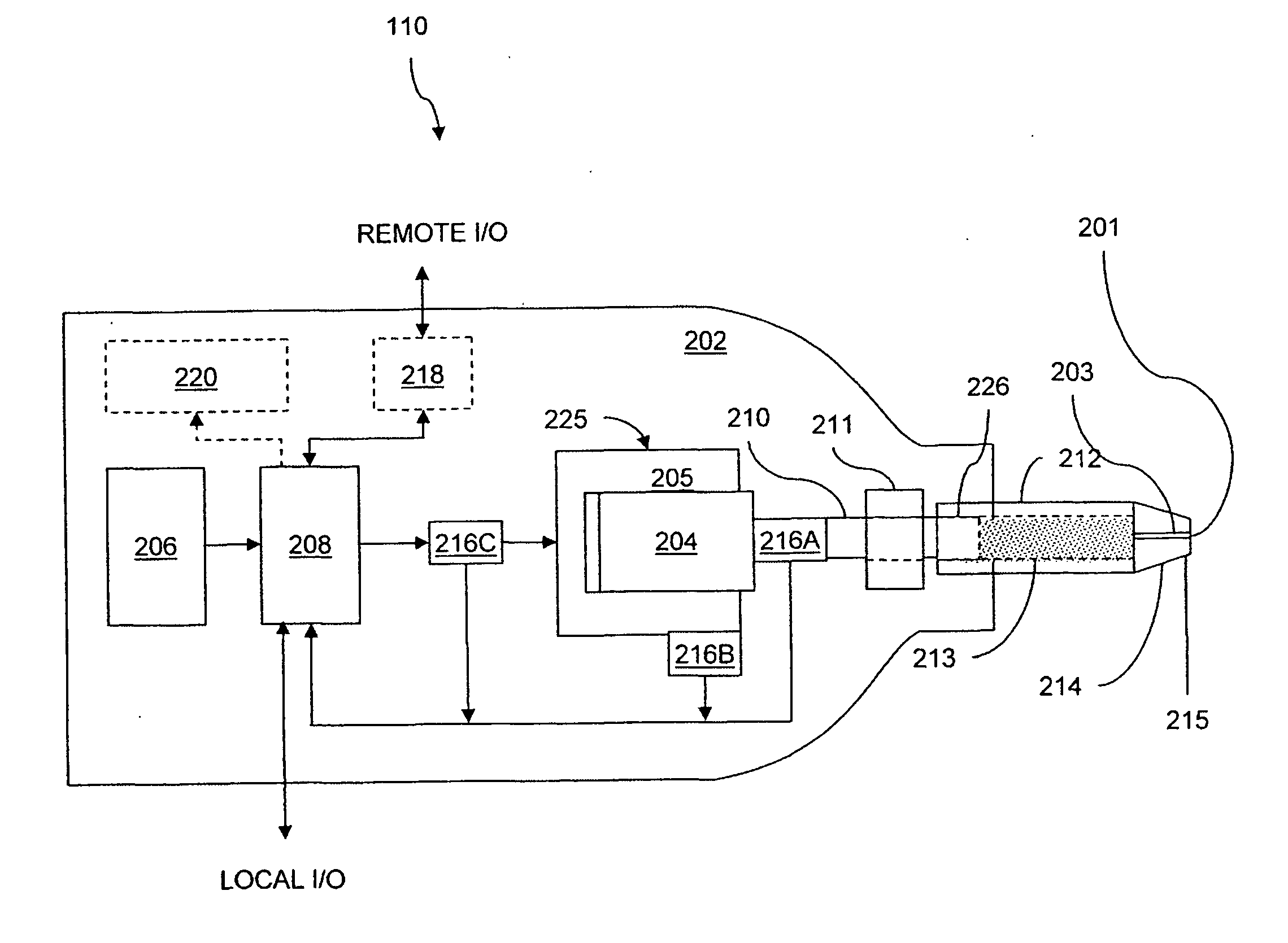
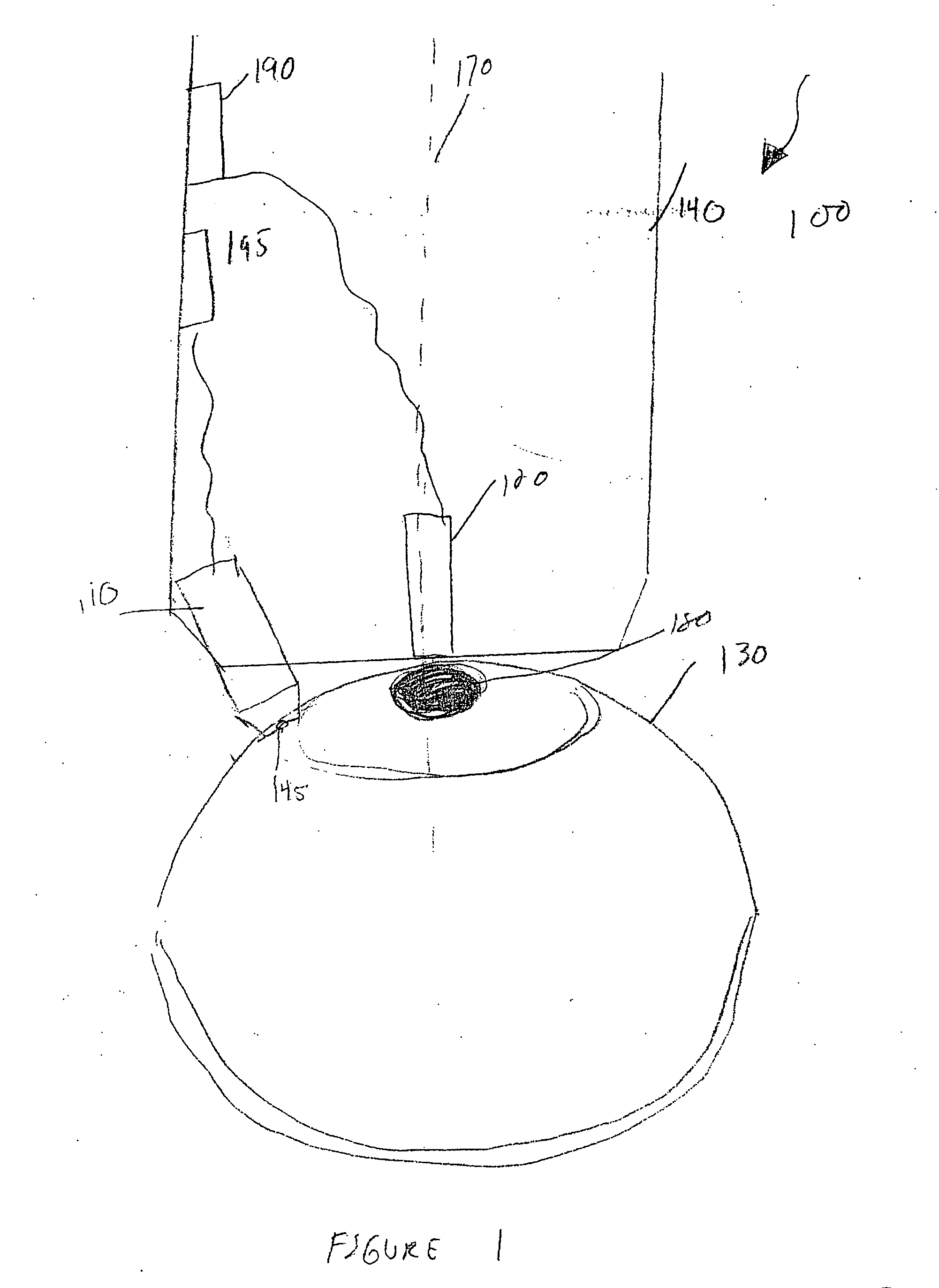
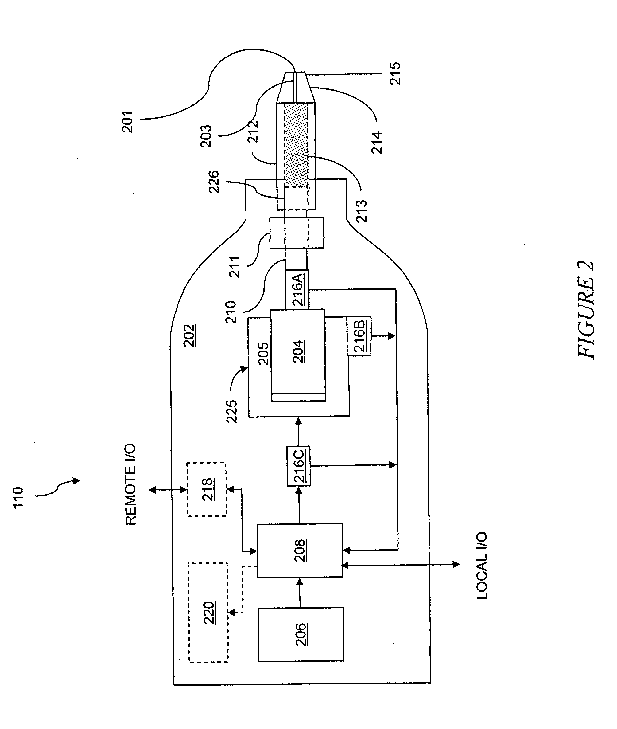
[0003] A needle-free jet injector may be used in order to reduce the risk of infection or damage to a patient's eye, as well as reducing the pain and anxiety of a needle into the eye. A delivery system for transferring a substance into an eye of an animal includes a needle-free injector. The needle-free injector includes a reservoir for storing the substance to be transferred to the eye, a nozzle in fluid communication with the reservoir, and a controllable electromagnetic actuator in communication with the reservoir. The delivery system can further include patient positioning mechanism to position the needle-free injector against a head of patient to direct the needle-free injector to inject a jet of the substance into the eye.

Problems solved by technology

Delivery of the drug by a needle causes increased risk of infection to the eye, as well as further damage to different regions of the eye.
Further, injections with a needle cause increased anxiety and potentially pain to a patient.

Method used


Image

  • Controlled needle-free eye injector
  • Controlled needle-free eye injector
  • Controlled needle-free eye injector

Examples


exemplary embodiment 500

[0079] An exemplary embodiment 500 of the needle-free injector 110 of the eye injector 100 is shown in FIG. 5. The needle-free injector 110 includes a controllable electromagnetic actuator 502 abutting one end to a pusher rod 506. The axis of the pusher rod 506 is collinear with the longitudinal axis of the actuator 502 and slides through a bearing 508 to inhibit radial movement. A mounting adapter 512 is provided at a distal end of the device 500 for mounting a syringe 510. A plunger of the syringe (not shown) resides within the mounting adapter 512 abutting the other end of the pusher rod 508. A power source, such as a rechargeable capacitor 512 is disposed proximal to the actuator 502 for inducing currents within the actuator 502. The needle free injector 500 also includes a button 514 to initiate an injection and a controller 516 to control application of the power source to the actuator 502. The button 514 can alternatively be positioned on the housing 140 of the eye injector, ...

exemplary embodiment 600

[0080] An exemplary embodiment 600 of a smaller, needle free injector 110 of the eye injector 100 is shown in FIG. 6. The device 600 includes a compact electromagnetic actuator 602 having a distal force plate 604 adapted to abut a proximal end of a plunger 606 of a syringe 608. The needle-free injector 600 also includes a mounting member 612 to which a proximal end of the syringe 608 is coupled. A power source 614 is also disposed proximal to the actuator 602, the different components being secured with respect to each other within a housing 616.

[0081] Referring to FIG. 7, in more detail, the compact controllable electromagnetic actuator 602 includes a ferromagnetic shell 722 including a central magnetic core 720 capped by a ferromagnetic end cap 706. A coil assembly 705 is slidably disposed within an annular slot of the magnet assembly floating freely within the slot. The distal end of the shell 722 includes one or more extensions 724 that continue proximally from the distal end of...


PUM


Abstract

An eye injector for transferring a substance across the surface of the eye of an animal includes a needle-free injector and a patient positioning mechanism. The needle-free injector includes a reservoir for storing the substance to be transferred, a nozzle in fluid communication with the reservoir; and a controllable electromagnetic actuator in communication with the reservoir. The eye injector can also include a targeting light source for directing a beam of light into a pupil of the eye. The needle-free injector can be positioned adjacent to the lens of the eye, therefore producing a jet that intersects with the beam of light at a point in the retina.

Description

RELATED APPLICATION [0001] This application claims the benefit of U.S. Provisional Application No. 60 / 735,713, filed on Nov. 11, 2005. The entire teachings of the above application are incorporated herein by reference.BACKGROUND OF THE INVENTION [0002] Ocular injections are often used for treatment of various diseases of the eye, for example glaucoma and various diseases causing vision loss. The treatments of such diseases generally require the injection of a treatment drug into the eye, using a conventional needle. Delivery of the drug by a needle causes increased risk of infection to the eye, as well as further damage to different regions of the eye. Further, injections with a needle cause increased anxiety and potentially pain to a patient. SUMMARY OF THE INVENTION [0003] A needle-free jet injector may be used in order to reduce the risk of infection or damage to a patient's eye, as well as reducing the pain and anxiety of a needle into the eye. A delivery system for transferring...

Claims


Application Information

Patent Timeline
IPC IPC(8): A61M35/00
CPCA61F9/0017A61F9/0026A61M5/30A61M5/31525A61M5/427A61M5/46A61M5/482A61M5/484A61M2005/3125A61M2005/31588A61M2205/3553A61M2205/3561A61M2205/3584A61M2205/587
Inventor HUNTER, IAN W.TABERNER, ANDREW T.WENDELL, DAWN M.HOGAN, NORA CATHERINEHEMOND, BRIAN D.TSENG, CHING-HUA
Owner PFIZER INC
Learn More