Power control method and system

Inactive Publication Date: 2007-06-07
HITACHI LTD
View PDF6 Cites 42 Cited by
  • Summary
  • Abstract
  • Description
  • Claims
  • Application Information

AI Technical Summary

Benefits of technology

[0008] Devices are set and installed such that control signals (including unauthorized power control requests and power control requests) do not directly reach a BMC or similar hardware devices residing on a server for processing remote power control requests from the outside, and a management server is installed instead for collectively managing power control requests from clients. Only when the management server receives a power control request and successfully authenticates the power control request, the management server conducts the power control for the client. In this way, the server remote power control can be conducted exclusively by the reliable management controller to ensure the security.
[0009] In addition to the authentication of a power control request by the management server, a hardware device responsible for the power control may also authenticate a power control request made by the management server. The management server may simply receive a comb

Problems solved by technology

A user authentication function of BMC simply stores a combination of a user ID with a password, which is compared for user authentication, and is therefore limited in hardware, has no margin in selecting the authentication scheme, and cannot ensure a higher level of security.
The foregoing limitations of the BM

Method used


Image

  • Power control method and system
  • Power control method and system
  • Power control method and system

Examples


Embodiment Construction

[0018] In the following, embodiments of the present invention will be described in detail with reference to the accompanying drawings.

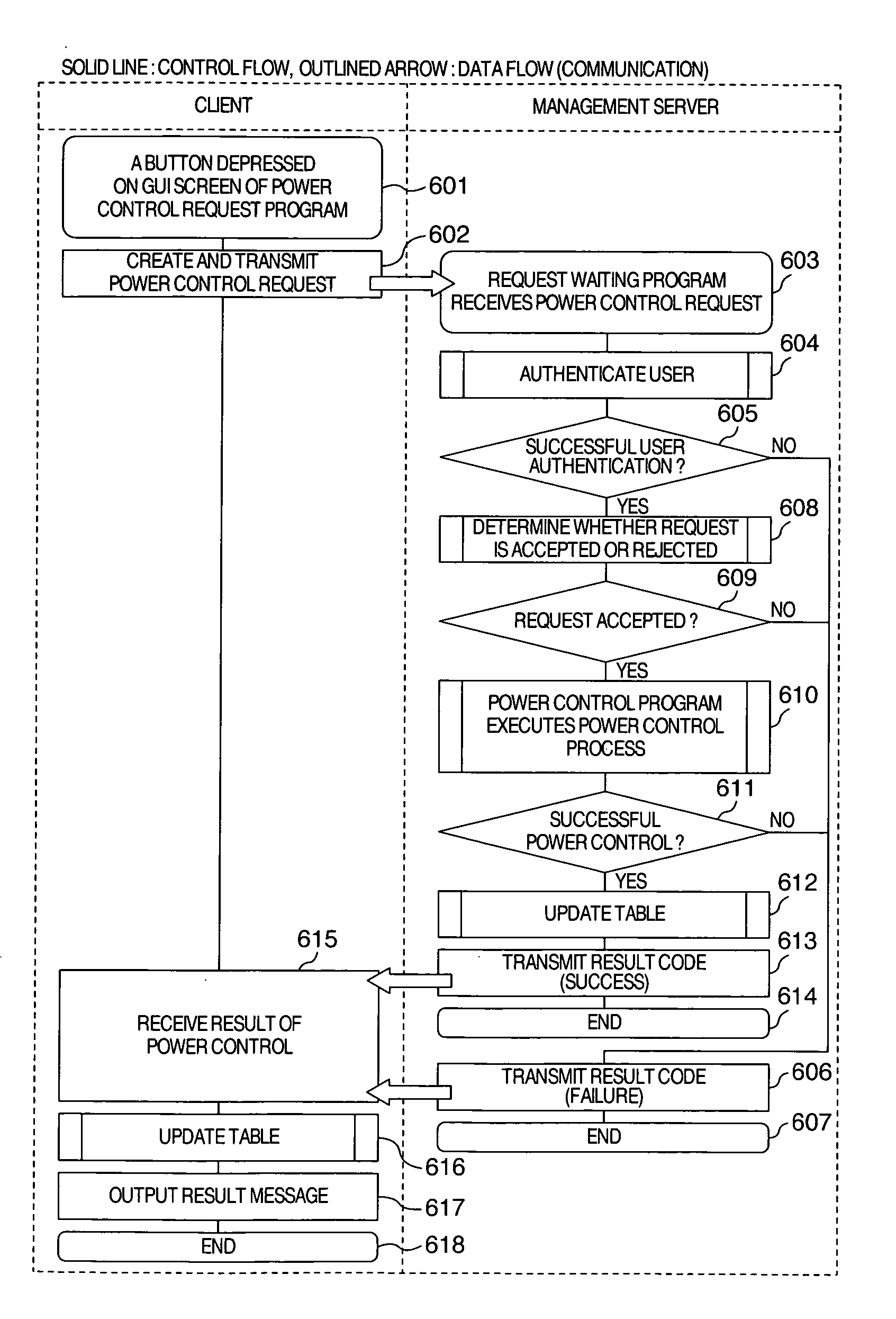
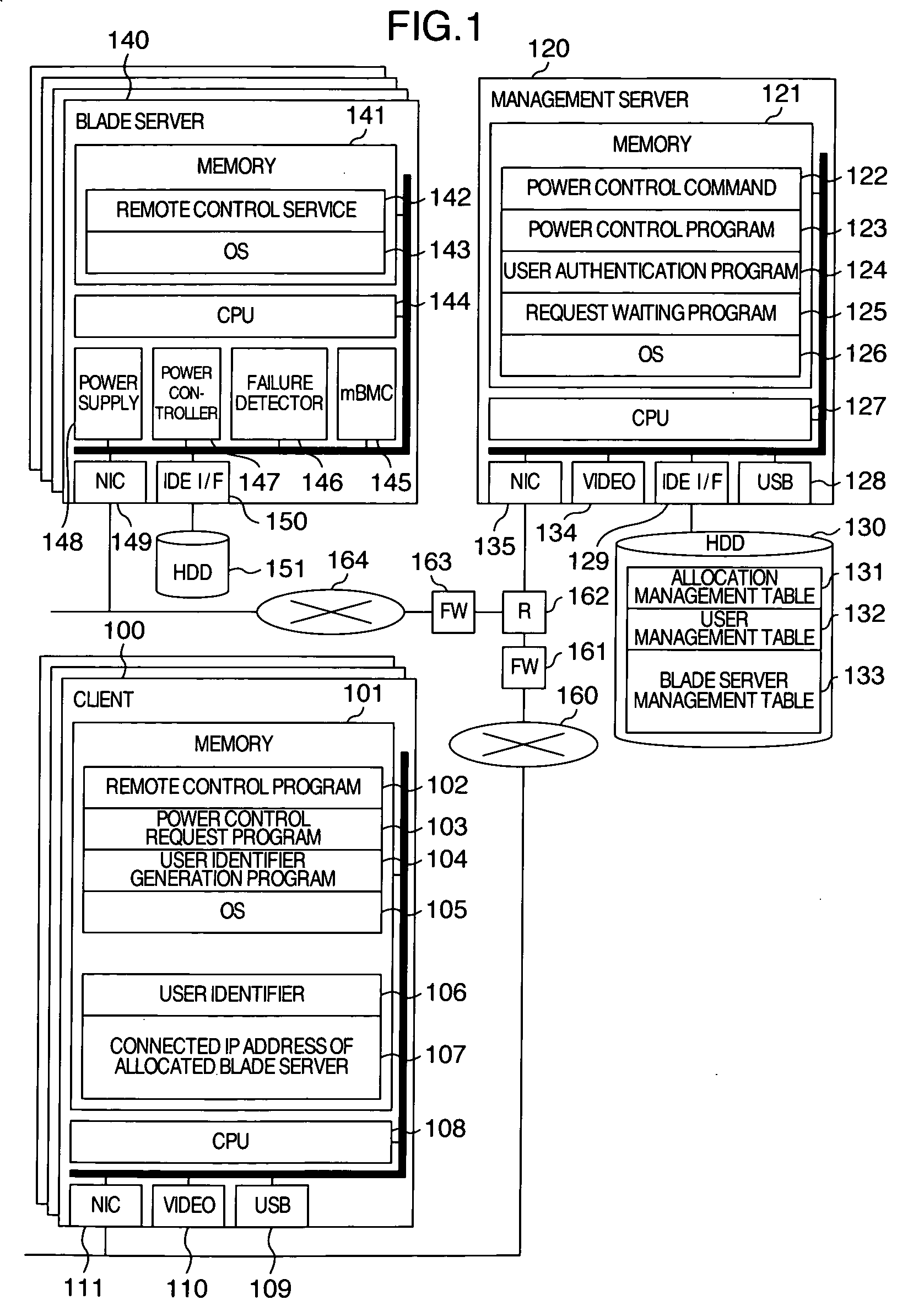
[0019]FIG. 1 is a block diagram generally illustrating the configuration of a system according to one embodiment of the present invention, where a management server, which is responsible for user authentication and remote power control in response to a request from a client, lends out blade servers.

[0020] A client 100 comprises a memory 101, a CPU 108, an USB (Universal Serial Bus) interface 109 which can be connected to a mouse, a keyboard, and a personal authentication device, a video interface 110 for outputting screen information to a display device connected thereto, and an NIC (Network Interface Card) 111. The memory 101 in turn stores a remote control program 102, a power control request program 103, a user identification generation program 104, and an operating system (OS) 105.

[0021] The remote control program 102 acquires a connected IP ad...


PUM


Abstract

A management server is installed for collectively accepting power control requests from clients. The management server authenticates a power control request received from a client with reference to a variety of tables which describe groups to which users and servers belong, respectively, and other attributes. Following successful authentication, the management server requests the blade server for remote power control.

Description

INCORPORATION BY REFERENCE [0001] This application relates to and claims priority from Japanese Patent Application No. 2005-347420 filed on Dec. 1, 2005, the entire disclosure of which is incorporated herein by reference. BACKGROUND OF THE INVENTION [0002] The present invention relates to a remote power control method and system for a computer system. [0003] An existing power control technique authenticates a remote power control requester with a combination of a user ID with a password, immediately determines whether or not the requested power control should be conducted in response to the result of successful authentication, and conducts the remote power control. This technique may be applied to configure a system which comprises one or a plurality of servers that are waiting at all times. In response to a request for utilization from a client, part or all of resources provided by the waiting servers are allocated exclusively for the client. After the client has utilized the resou...

Claims


Application Information

Patent Timeline
IPC IPC(8): G06F1/00G06F21/31G06F21/33
CPCG06F21/41H04L63/104
Inventor TAKAHASHI, SHUTAUDO, RYUTA
Owner HITACHI LTD
Why Eureka
Try Eureka