Underground fuel tank vent valve

a fuel tank and vent valve technology, applied in the direction of valve operating means/releasing devices, functional valve types, transportation and packaging, etc., can solve the problems of difficult to consistently control the low pressure cracking and sealing, detrimental to the function and preciseness, and difficult to consistently control the low cracking and sealing desired

Inactive Publication Date: 2007-06-14
OPW FUELING CONTAINMENT SYST INC
View PDF52 Cites 18 Cited by
  • Summary
  • Abstract
  • Description
  • Claims
  • Application Information

AI Technical Summary

Benefits of technology

[0009] Another objective of the invention has been to eliminate functional mechanical structures in such a vent v

Problems solved by technology

This situation may occur, for example, where an operator fails to connect a vacuum relief line to a delivery truck as the tank is filled.
The mechanical nature of their structures, when combined with harsh use environments, however, makes it difficult to consistently control low pressure cracking and sealing in a small number of instances in extreme ranges of use.
These circumstances could be detrimental to the function and to t

Method used


Image

  • Underground fuel tank vent valve
  • Underground fuel tank vent valve
  • Underground fuel tank vent valve

Examples


Embodiment Construction

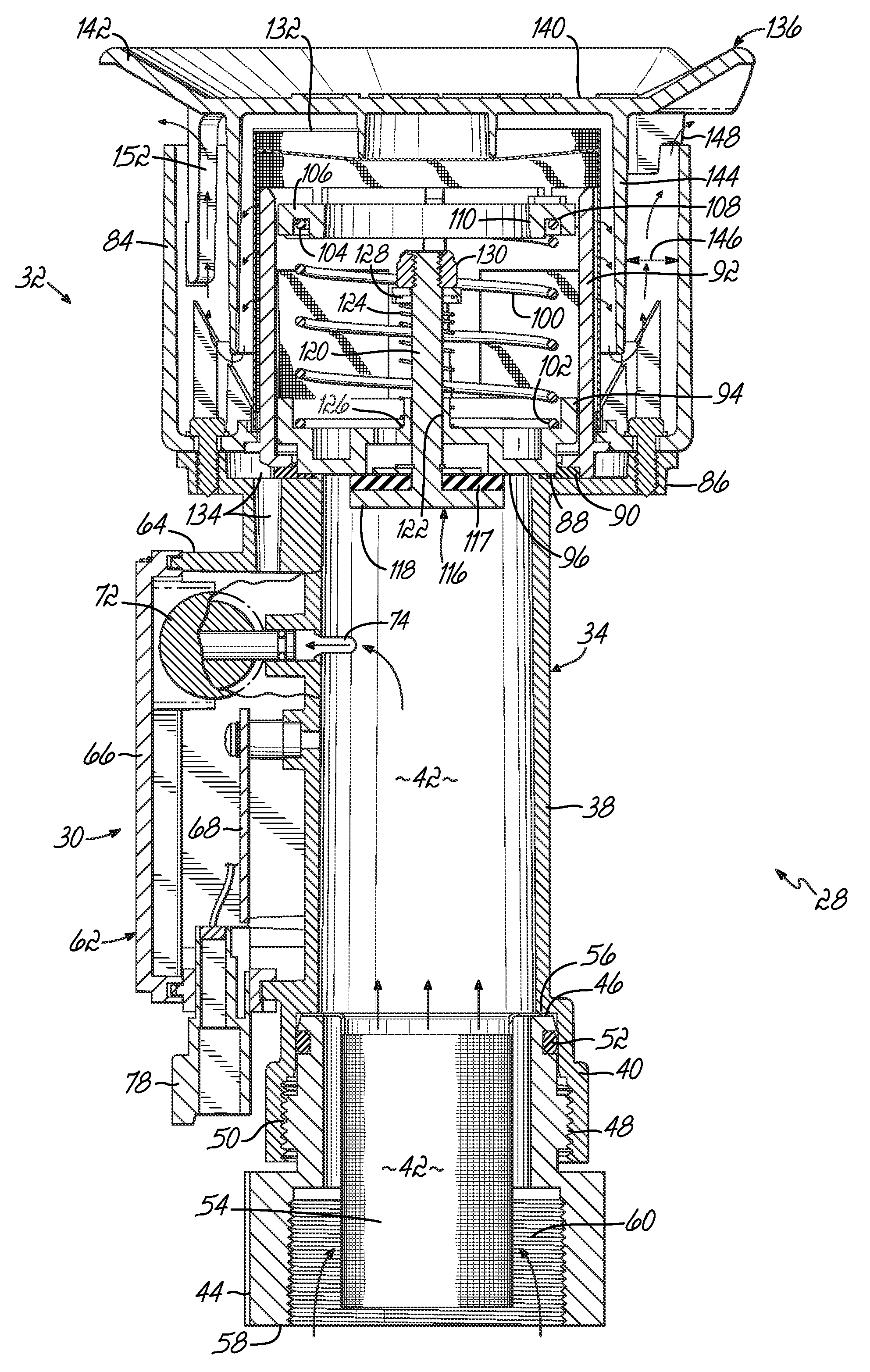
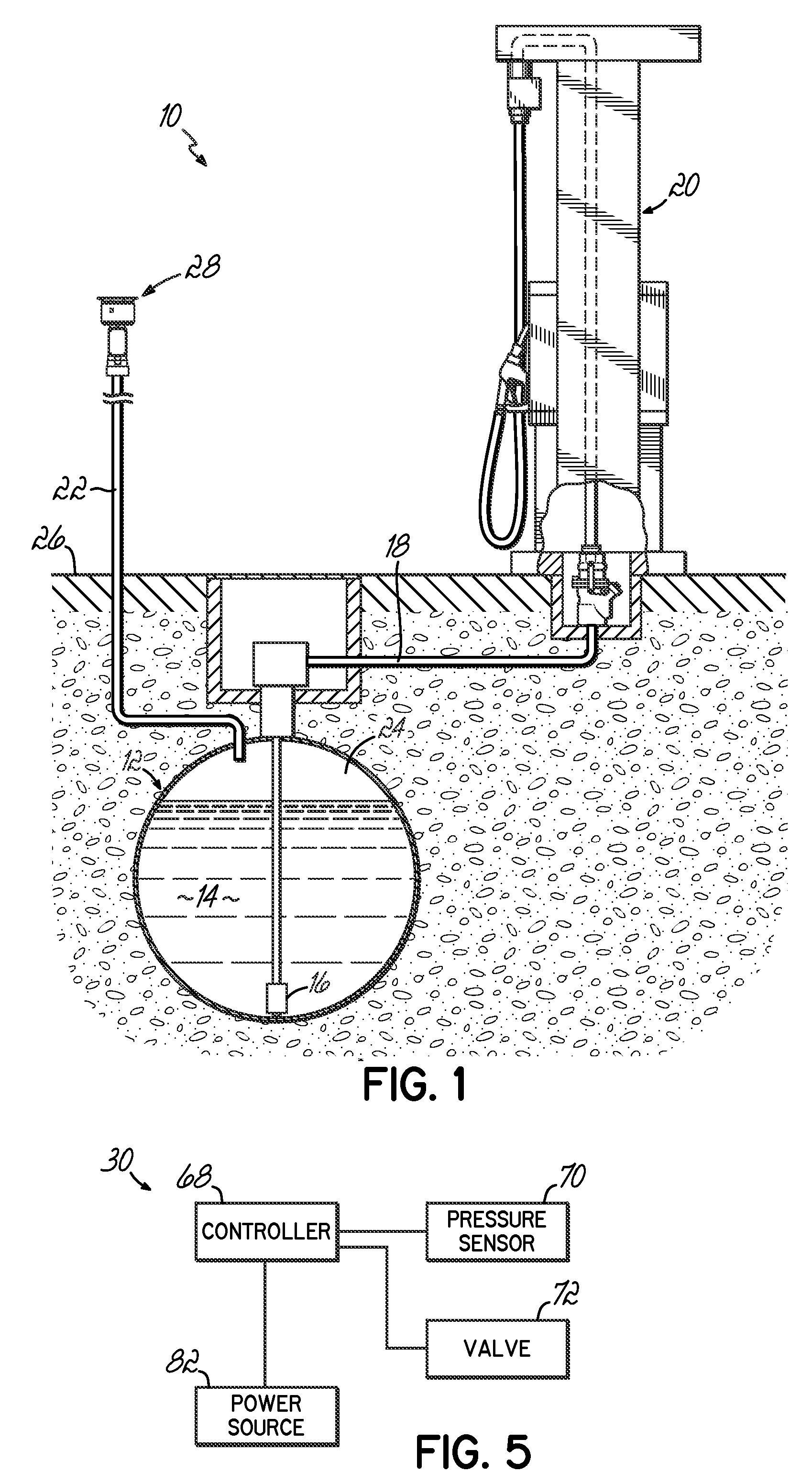
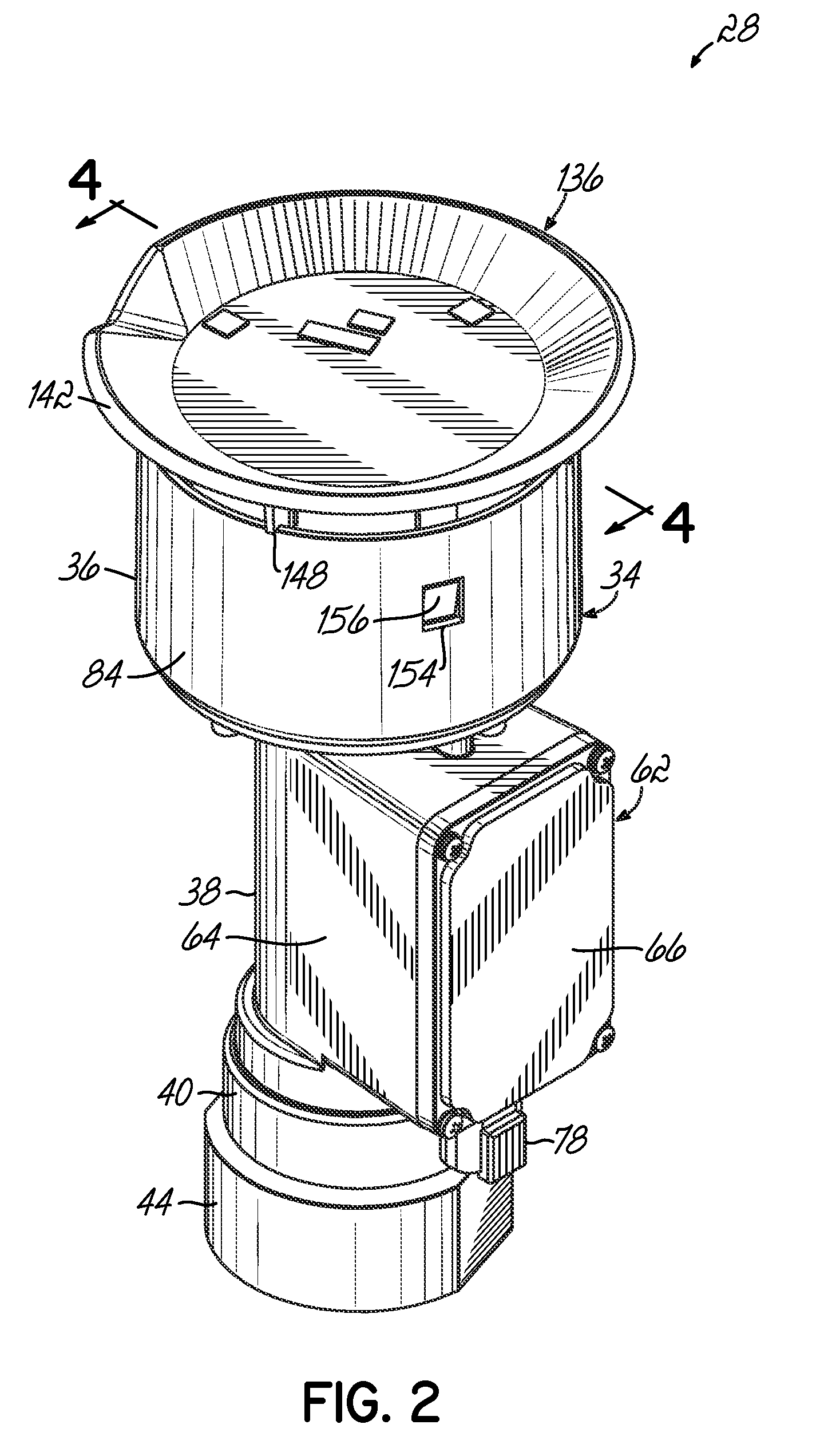
[0023] An exemplary fuel dispensing system 10 in accordance with the invention is shown in FIG. 1 and generally includes an underground fuel tank 12 for storing a fuel 14, and a submersible pump 16 located within tank 12 and coupled to a fluid conduit line 18 that transports the fuel 14 under pressure to one or more dispensers 20. The fuel dispensing system 10 also generally includes a vent line 22 that fluidly couples the vapor or ullage space 24 of the tank 12 to the atmosphere above the ground 26. The vent line 22 includes a pressure / vacuum (PV) vent valve 28 that permits fluid flow out of or into the tank 12 under certain design pressure differentials. For instance, if the pressure in tank 12 exceeds atmospheric pressure by a specified amount, the PV vent valve 28 opens to allow fluid, such as fuel vapor, air, etc. in the ullage space 24 to flow out of the tank 12, vent line 22, and to the atmosphere to reduce or equalize the pressure in tank 12. Similarly, if the pressure in th...


PUM


Abstract

A vent valve for a fuel tank includes a valve housing having a first valve mechanism movable between an open and closed position and a second valve mechanism movable between an open and closed position. The first valve mechanism opens to vent the tank at a first design pressure differential between the tank pressure and atmospheric pressure and the second valve mechanism opens to vent the tank at a second design pressure differential that is greater than the first design pressure differential. The first valve mechanism is an electronic valve mechanism and the second valve mechanism is a mechanical valve mechanism. A method of venting a fuel tank includes opening the first valve mechanism to establish fluid communication between the tank and atmosphere at the first design pressure differential and opening the second valve mechanism to establish fluid communication between the tank and atmosphere at the second design pressure differential.

Description

CROSS REFERENCE TO RELATED APPLICATIONS [0001] This application claims priority to provisional patent application Ser. No. 60 / 749,912 filed on Dec. 13, 2005, the disclosure of which is expressly incorporated by reference herein in its entirety.FIELD OF THE INVENTION [0002] This invention relates to venting of underground fuel tanks and more particularly to improved vents providing more accurate and consistent venting at low pressure differentials, while accommodating high volume vent flow at higher pressure differentials. BACKGROUND OF THE INVENTION [0003] Currently, underground fuel tanks are connected to a vent line and an above-surface vent for venting vapors at positive pressures in excess of ambient pressures and for inflow of atmospheric air in the event of a vacuum or negative pressure in the tank. Such pressure differentials may result from thermal expansions and contractions resulting from temperature changes and the like, for example. Tanks are individually vented or a plu...

Claims


Application Information

Patent Timeline
IPC IPC(8): G05D7/06
CPCF16K24/04F16K31/363Y10T137/7761
Inventor MANGER, PETER E.
Owner OPW FUELING CONTAINMENT SYST INC
Why Eureka
Try Eureka