Combined track-railbed joining apparatus

a technology of joining apparatus and railbed, which is applied in the direction of toys, constructions, and ways, etc., can solve the problems of not being able to prevent longitudinal, connectors, or fishplates, and being rather delicate objects, and achieves simple configuration, easy replacement, and easy and inexpensive construction.

Inactive Publication Date: 2007-06-14
MICRO TRAINS LINE
View PDF15 Cites 1 Cited by
  • Summary
  • Abstract
  • Description
  • Claims
  • Application Information

AI Technical Summary

Benefits of technology

[0014] Yet another object of the instant invention is to provide a system which will protect track connectors from damage.
[0017] A further object of the invention is to provide a system which is easy and inexpensive to construct and which incorporates structures having simple configurations.
[0018] Another object of the invention is to provide a joining element which may easily be replaced in the event of damage or breakage.

Problems solved by technology

The connectors are not intended to provide a physical restraining system for the track, and, although the connectors will prevent lateral movement of track sections relative to one another, they will do very little to prevent longitudinal movement, which, if not prevented, will allow the track sections to separate from one another.
The connectors, or fishplates, are rather delicate objects, particularly in the smaller gauges, e.g., N scale and smaller.
The connectors extend beyond the ends of the rails, and as such, are subject to impact, which may result in disfigurement, following which the connectors may not be operational to join sections of tracks or to provide an electrical connection therebetween.
Because the connectors are easily damaged or distorted, assembly of sectional track must be performed by a person having a high degree of manual dexterity.
Conventional, small-scale track is not suitable for use by children, and, for some adults, may be difficult to manipulate.
This results in an enlargement of the connector, which in turn results in poor electrical connection between track sections upon reassembly.
Poor electrical connection between track sections will result in poor operation of the model trains which are run on the track.
Although some forms of joining systems have been developed which provide for the longitudinal and lateral alignment of sectional track, known systems involve complex structures which are difficult to form and which are not easily injection molded.
Known structures are subject to breakage, and because known joining structures are either permanently fixed to a track section or integrally formed therewith, they are not repairable.
Thus, breakage of a small part of a track section results in destruction of the entire track section.

Method used


Image

  • Combined track-railbed joining apparatus
  • Combined track-railbed joining apparatus
  • Combined track-railbed joining apparatus

Examples


Embodiment Construction

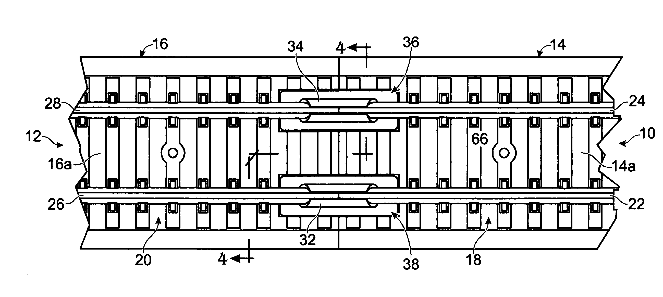
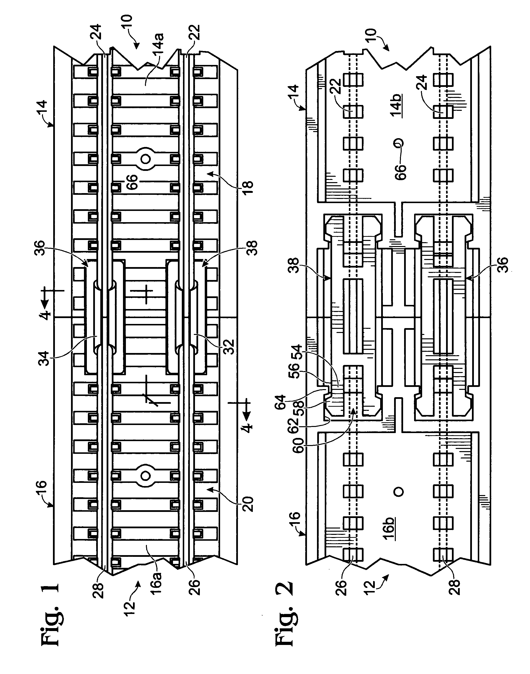
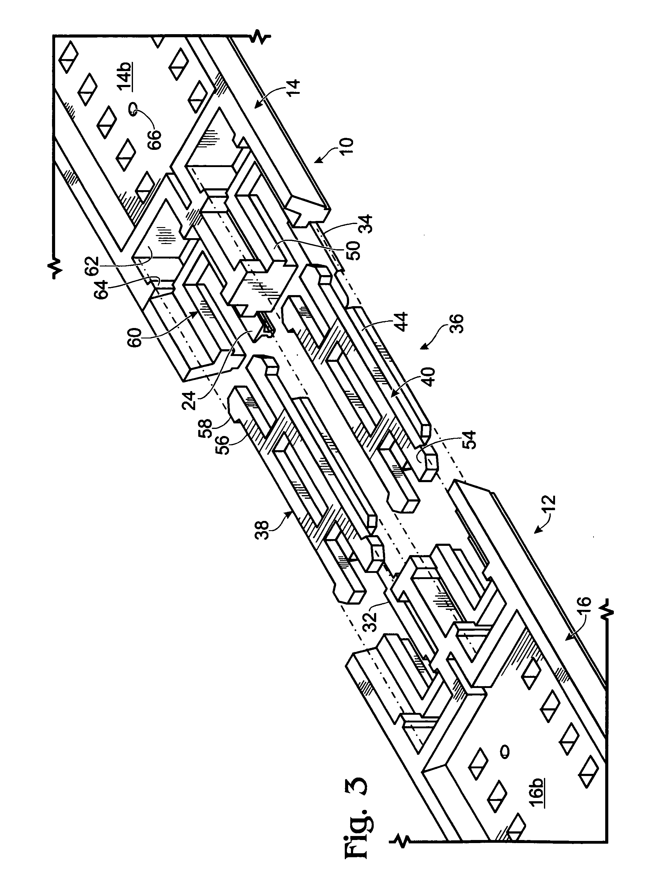
[0026] Referring now to FIGS. 1 - 4, portions of two pieces of sectional combined model railroad track and railbed are shown generally at 10 and 12. Each section of track includes an elongate railbed 14, 16 having upper surfaces 14a, 16a and lower surfaces 14b, 16b, respectively.

[0027] An array 18, 20, of model railroad ties is located on the upper surface 14a, 16a of each railbed. Rails 22, 24 and 26, 28 are positioned in a spaced apart relationship on tie arrays 18, 20, respectively. The rails are electrically conductive and are generally formed from brass or nickel-silver alloy.

[0028] Referring momentarily to FIG. 4, rails 24, 26 are shown in end view. Each rail includes a base, such as 26a, having flanges 26b extending from either side thereof. A central web 26c extends upward from the base and connects with a rail head 26d. The rails are secured to the ties by means of rail “spikes”30 which extend over the rail flanges to hold the rails on the ties. In this embodiment, the ra...


PUM


Abstract

A joining apparatus is provided for a model railroad track, wherein the model railroad track includes a pair of combined track-railbed sections, with each end thereof configured for abutting an end of another combined track-railbed section, including a tie array disposed on an upper portion of each railbed and a pair of spaced apart rails fixed thereto, wherein the rails are electrically and physically joined to a rail on an abutted rail by a rail connector. Each combined track-railbed section includes a joining element retainer located adjacent each end of the section, underlying the railbed adjacent an end of each rail fixed to the railbed. A joining element is removably retainable in each joining element retainer for providing horizontal, vertical and longitudinal alignment between abutted combined track railbed sections.

Description

FIELD OF THE INVENTION [0001] The instant invention relates to model railroad track and specifically to a track joining apparatus which securely holds two sections of a combined track-roadbed assembly together and provides horizontal, vertical and longitudinal alignment therefore. BACKGROUND OF THE INVENTION [0002] Sectional model railroad track has been constructed in a variety of forms. In the simplest form, a section of track includes a pair of spaced apart, electrically conductive rails and an arrangement of ties extending between the rails, the ties being joined together to form the track section into the desired configuration, i.e., straight, curved with a variety of radii, or turnouts, with a variety of frog ratios. [0003] Another form of sectional track includes the aforementioned elements which are secured to a section of roadbed to eliminate the necessity of laying a separate roadbed and then laying the sectional track on top thereof. [0004] The simplest joining system con...

Claims


Application Information

Patent Timeline
Patent Type & Authority Applications(United States)
IPC IPC(8): E01B23/00
CPCA63H19/30A63H19/32
Inventor WARD, STEVE R.
Owner MICRO TRAINS LINE
Why Eureka
Try Eureka