Motor driving control device

a control device and motor technology, applied in the direction of motor/generator/converter stopper, dynamo-electric gear control, motor/generator/converter stopper, etc., can solve the problem of inability to accurately perform polarity checking, the estimation technique cannot apply to the direction of the d axis estimation, and the inability to estimate whether the direction of the d axis lies within the rang

Active Publication Date: 2007-06-14
SANYO ELECTRIC CO LTD
View PDF8 Cites 47 Cited by
  • Summary
  • Abstract
  • Description
  • Claims
  • Application Information

AI Technical Summary

Benefits of technology

[0166] Even with the configuration of this embodiment, checking of the polarity is performed by using a second-harmonic-extracted component of current. This makes it possible to achieve the same effects as those achieved in the first embodiment, and thereby offer stable polarity checking.

Problems solved by technology

However, such an estimation technique cannot be applied to estimation of the direction of the d axis (i.e. it is impossible to estimate whether the direction of the d axis lies within the range from 0 to π or within the range from π to 2π in electrical angle).
However, in the conventional technique typified by the configuration shown in FIG. 43, as a result of checking of the polarity being performed by using the difference between the positive and negative amplitudes of the γ-axis current iγ including a direct-current component (and a low-frequency component that can be regarded as a direct-current component), the following problems arise.
In other words, these influences make it impossible to perform checking of the polarity correctly.

Method used


Image

  • Motor driving control device
  • Motor driving control device
  • Motor driving control device

Examples


first embodiment

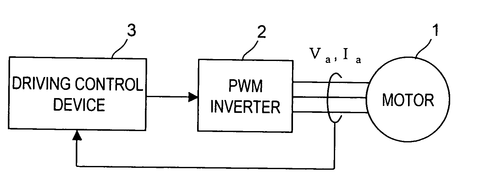
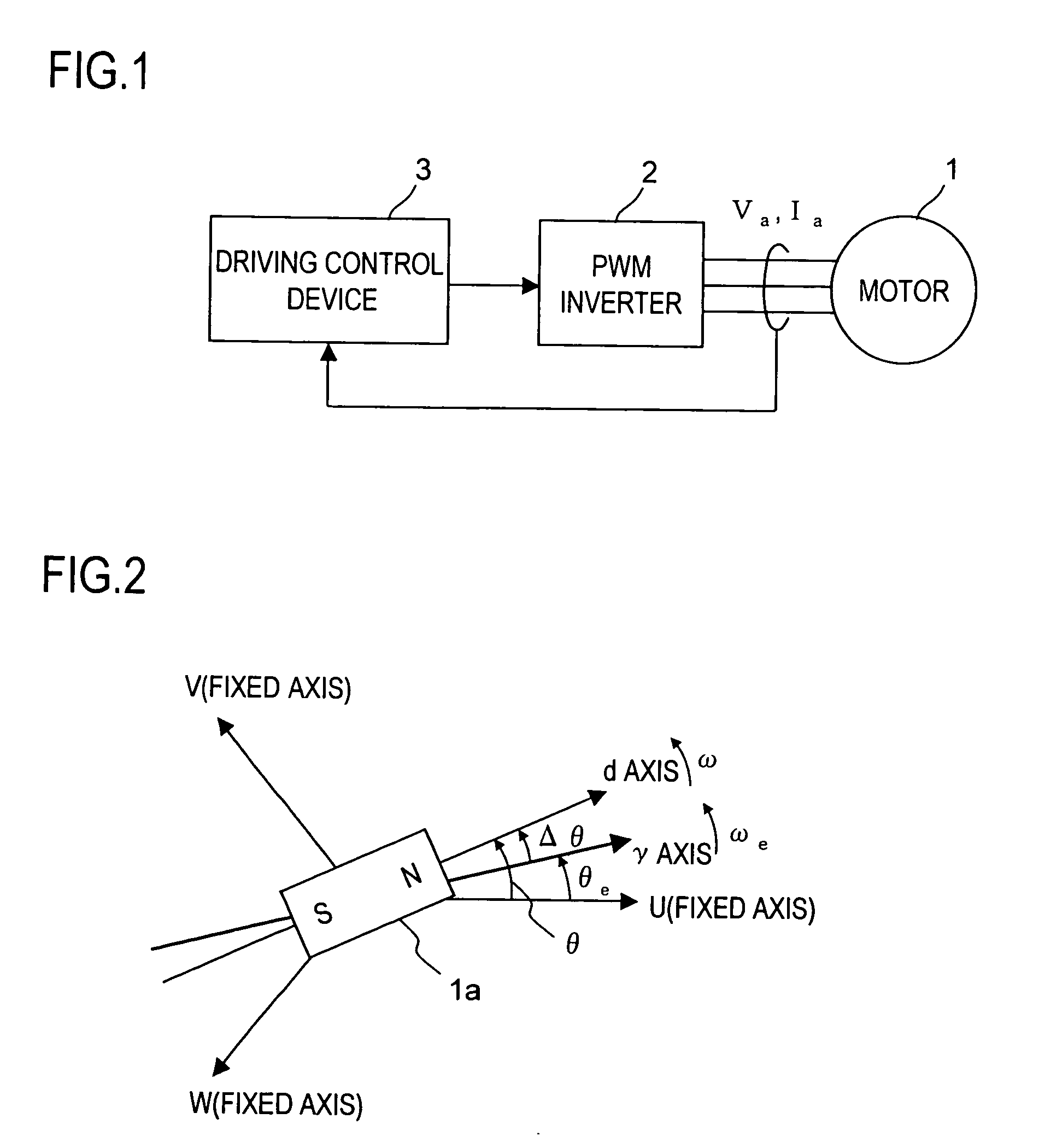
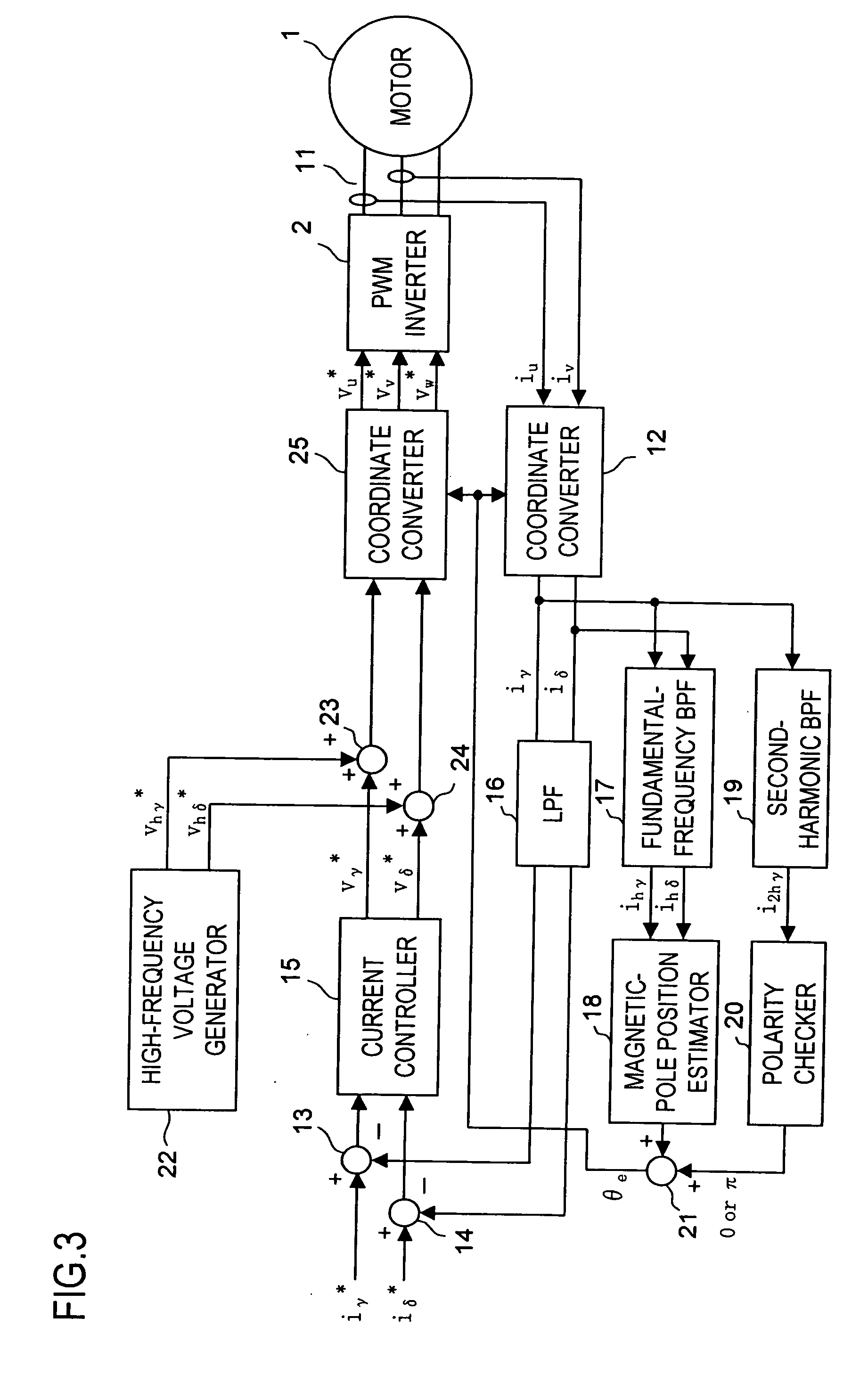
[0103]FIG. 3 is a configuration block diagram of the motor drive system of a first embodiment of the present invention. The driving control device of this embodiment is composed of a current detector 11, a coordinate converter 12, subtracters 13 and 14, a current controller 15, an LPF (low-pass filter) 16, a fundamental-frequency BPF (band-pass filter) 17, a magnetic-pole position estimator 18, a second-harmonic BPF (band-pass filter) 19, a polarity checker 20, an adder 21, a high-frequency voltage generator 22, an adder 23, an adder 24, and a coordinate converter 25. The individual functional blocks of the driving control device of this embodiment and all the embodiments described hereinafter can freely use, whenever necessary, all the values generated within the driving control device.

[0104] The current detector 11 is implemented with, for example, a Hall device, and detects the U-phase current iu and the V-phase current iv of the motor current Ia fed from the PWM inverter 2 to t...

second embodiment

[0157] Next, a second embodiment of the present invention will be described. FIG. 25 is a configuration block diagram of the motor drive system of the second embodiment. The driving control device of this embodiment differs from the driving control device shown in FIG. 3 only in that a second-harmonic BPF 19 and a polarity checker 20 shown in FIG. 3 are replaced with a second-harmonic BPF 19a and a polarity checker 20a. In other respects, the driving control device of this embodiment is the same as the driving control device (of the first embodiment) shown in FIG. 3. In FIG. 25, such functional blocks as are found also in FIG. 3 are identified with the same reference numerals, and their explanations in principle will not be repeated.

[0158] The second-harmonic BPF 19a shown in FIG. 25 realizes not only the function of the second-harmonic BPF 19 shown in FIG. 3 that extracts the second-harmonic-extracted γ-axis current i2hγ but also the function of extracting the second-harmonic-extr...

third embodiment

[0180] Next, a third embodiment of the present invention will be described. FIG. 28 is a configuration block diagram of the motor drive system of the third embodiment. The driving control device of this embodiment differs from the driving control device shown in FIG. 3 only in that a polarity checker 20 and a high-frequency voltage generator 22 shown in FIG. 3 are replaced with a polarity checker 20b and a high-frequency voltage generator 22b. In other respects, the driving control device of this embodiment is the same as the driving control device (of the first embodiment) shown in FIG. 3. In FIG. 28, such functional blocks as are found also in the figures (e.g. FIG. 3) of the already-described embodiments are identified with the same reference numerals, and their explanations in principle will not be repeated.

[0181] As is the case with the high-frequency voltage generator 22 shown in FIG. 3, the high-frequency voltage generator 22b generates high-frequency voltages vhγ* and vhδ c...


PUM


Abstract

In a motor driving control device, a high-frequency alternating voltage or rotation voltage (having a frequency of ωh) is applied to a motor so that magnetic saturation occurs in the motor, thereby extracting, from a γ-axis current, a high-frequency second-harmonic component (a frequency component of 2×ωh) that is obtained by attenuating at least a direct-current component of the γ-axis current. The polarity checker detects the polarity of the magnetic pole of the rotor based on the difference, caused by magnetic saturation, between the positive and negative amplitudes of the high-frequency second-harmonic component.

Description

[0001] This application is based on Japanese Patent Application No. 2005-354506 filed on Dec. 8, 2005, the contents of which are hereby incorporated by reference. BACKGROUND OF THE INVENTION [0002] 1. Field of the Invention [0003] The present invention relates to a motor driving control device that controls the driving of a motor, and more particularly to a motor driving control device that drives and controls the motor without the use of a magnetic-pole position sensor. [0004] 2. Description of Related Art [0005] There have conventionally been developed techniques for detecting the magnetic-pole position of a rotor of a motor without the use of a sensor. Some of such techniques propose to detect the polarity or the position of the magnetic pole of the rotor by exploiting injection of a high-frequency rotation voltage or a high-frequency rotation current. [0006] With reference to FIGS. 41 and 42, a polarity checking technique for a permanent-magnet synchronous motor will be describe...

Claims


Application Information

Patent Timeline
Patent Type & Authority Applications(United States)
IPC IPC(8): H02P21/00H02P6/06H02P6/18H02P6/08H02P6/182H02P6/28H02P21/13H02P21/22H02P27/04H02P27/08
CPCH02P21/0039H02P21/14H02P2203/11H02P21/24
Inventor TAKAO, HIROSHITOMIGASHI, YOSHIO
Owner SANYO ELECTRIC CO LTD
Why Eureka
Try Eureka