Optical microscope and spectrum measuring method

a spectrum measurement and optical microscope technology, applied in the field of optical microscope and spectrum measurement method, can solve the problems of difficult to change the laser light into a linear light beam having the same intensity, speckle noise, and the inability to uniformly illuminate the sample, etc., and achieve the effect of high accuracy measurement in a short period

Active Publication Date: 2007-06-14
NANOPHOTON
View PDF7 Cites 47 Cited by
  • Summary
  • Abstract
  • Description
  • Claims
  • Application Information

AI Technical Summary

Benefits of technology

[0007] The present invention has been accomplished in view of the above problems, and it is therefore an object of the inve...

Problems solved by technology

1331-1337, laser light is changed into linear light by the cylindrical lens, resulting in a problem in that the sample cannot be uniformly illuminated.
It is difficult to change the laser light into a linear light beam having uniform intensity.
There is another problem in that a speckle noise occurs and hinders high-accuracy observation.
This scattered light l...

Method used


Image

  • Optical microscope and spectrum measuring method
  • Optical microscope and spectrum measuring method
  • Optical microscope and spectrum measuring method

Examples


first embodiment

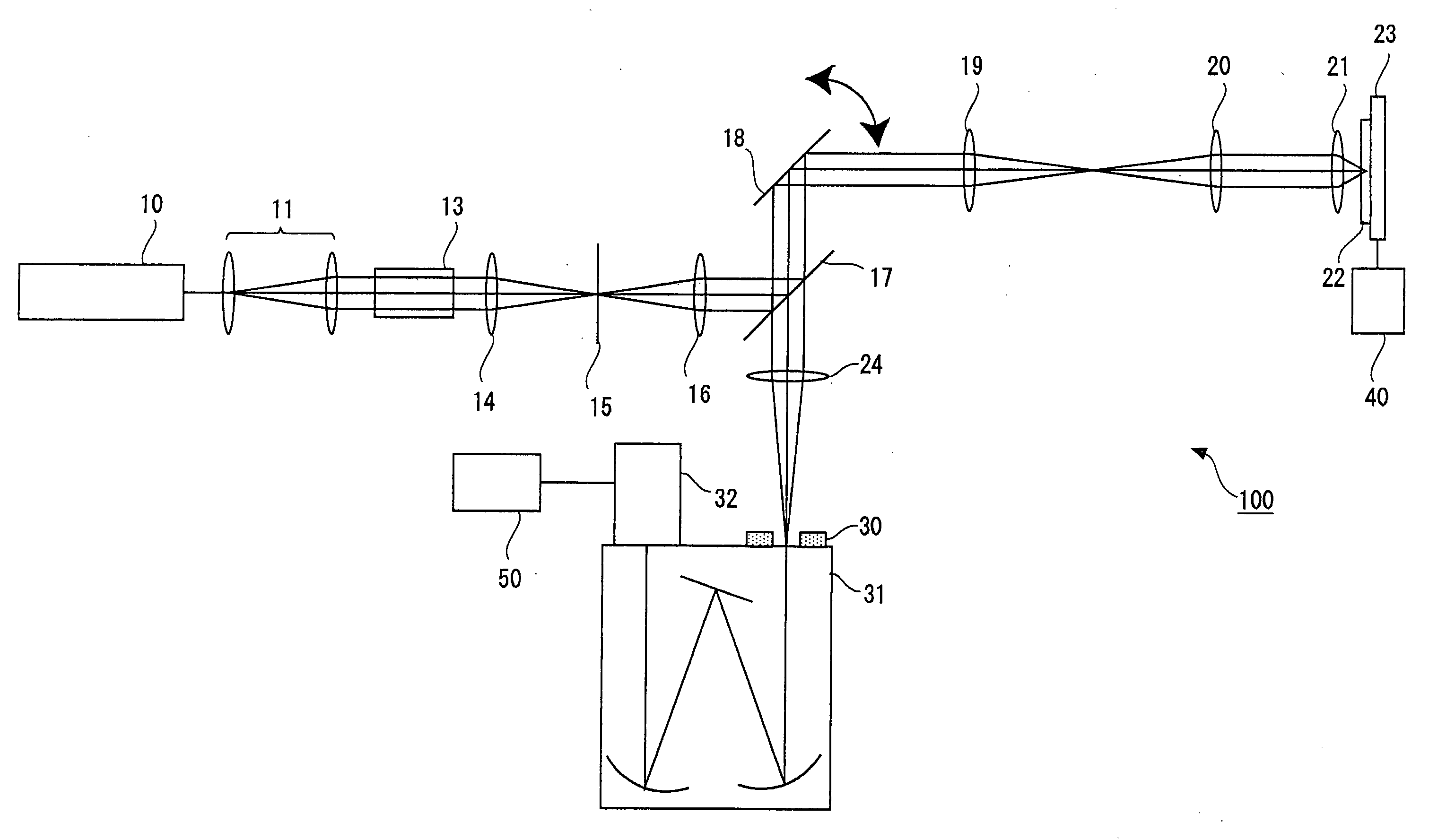
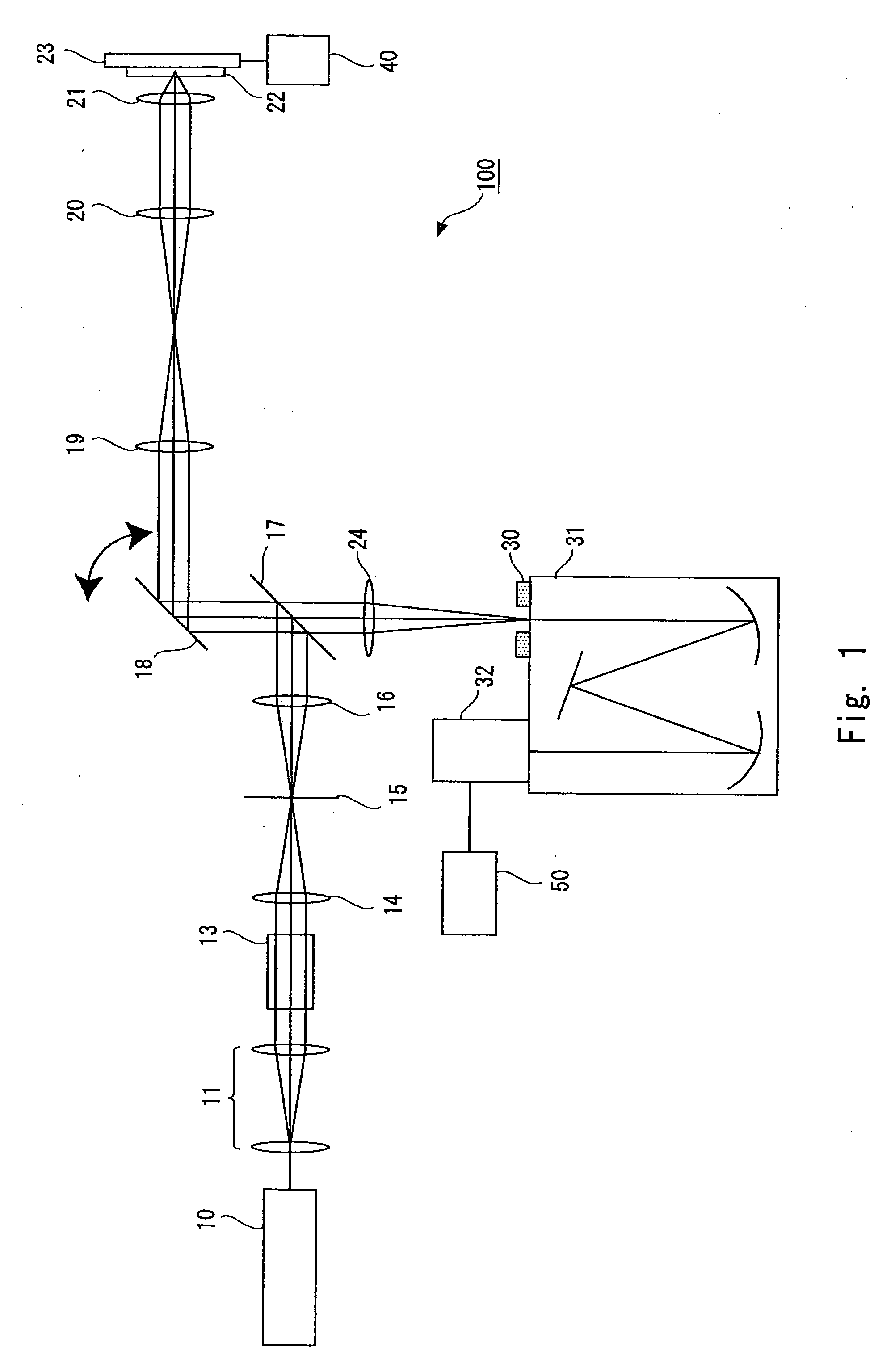
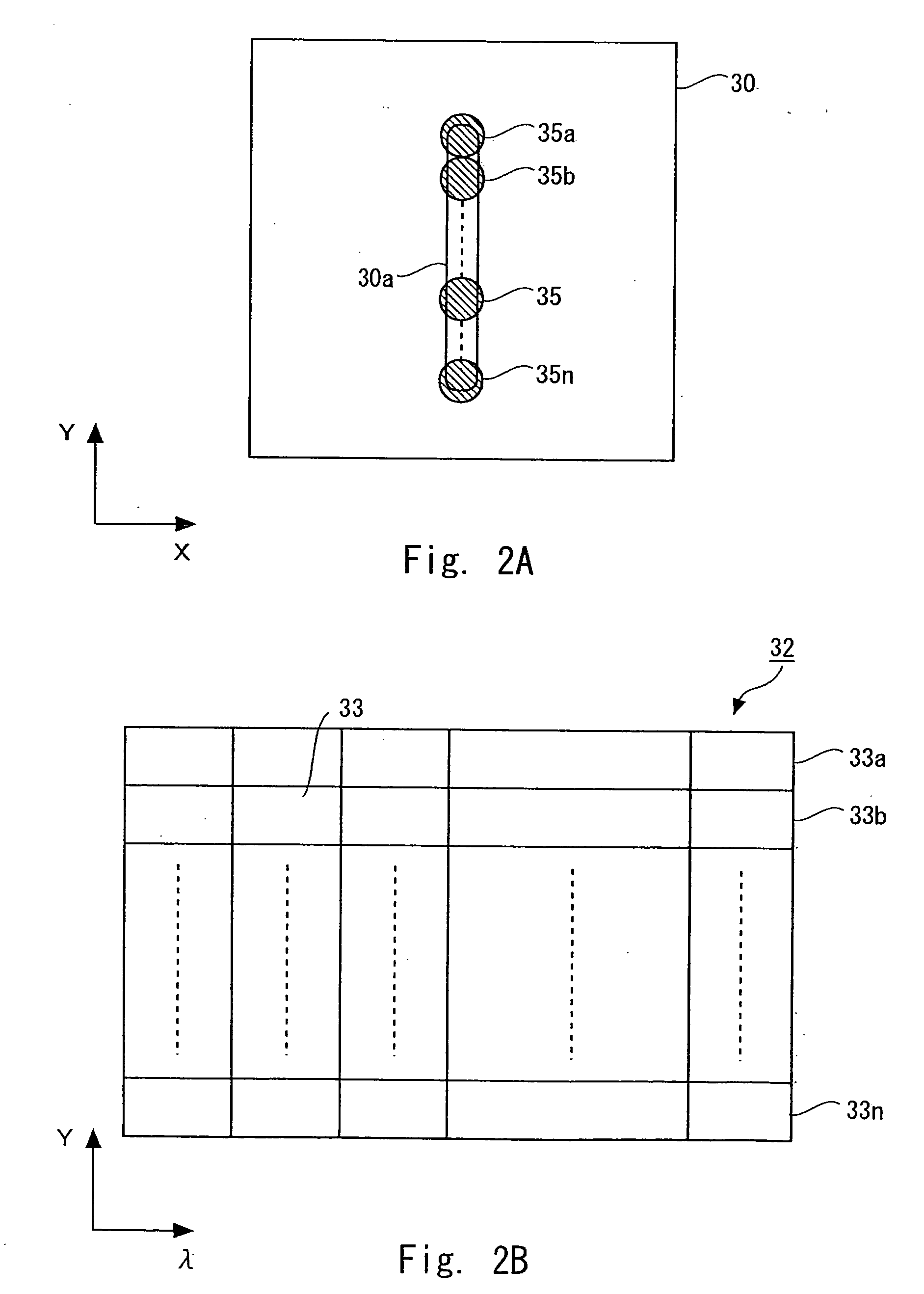
[0032] Referring to FIG. 1, an optical microscope according to a first embodiment of the present invention is described below. FIG. 1 schematically shows the structure of the optical microscope of this embodiment. An optical microscope 100 includes, as the structure for observing a sample 22, a laser light source 10, a beam expander 11, a Y-directional scanning unit 13, a lens 14, a diaphragm 15, a lens 16, a beam splitter 17, an X-directional scanning mirror 18, a lens 19, lens 20, an objective lens 21, a stage 23, a lens 24, a spectroscope 31, a detector 32, a stage driver 40, and a processor 50. The spectroscope 31 is provided with an entrance slit 30 on an incidence side.

[0033] The optical microscope 100 is a Raman microscope. The optical microscope allows light beam from the laser light source 10 to enter the sample 22 and detects Raman scattered light from the sample 22 with the detector 32. Further, the spectroscope 31 diffuses the Raman scattered light, and thus Raman spect...

second embodiment

[0072] Referring to FIG. 7, an optical microscope according to a second embodiment of the present invention is described next. FIG. 7 shows the structure of the optical microscope of the second embodiment. Incidentally, the optical microscope of this embodiment includes a cylindrical lens 51 in addition to the components of the optical microscope of the first embodiment. The cylindrical lens 51 is provided downstream of the lens 14. Incidentally, the basic structure of the optical microscope of this embodiment is the same as that of the first embodiment, so its description is omitted here. That is, components other than the cylindrical lens 51 are the same as those of the first embodiment.

[0073] As shown in FIG. 7, the cylindrical lens 51 is provided between the lens 14 and the diaphragm 15. The cylindrical lens 51 is a concave lens. The cylindrical lens 51 cancels out light components refracted in the Y direction by the lens 14 as a convex lens. Thus, the beam spot of the laser li...

third embodiment

[0076] Referring to FIG. 8, the structure of an optical microscope according to a third embodiment of the present invention is described next. FIG. 8 shows the structure of the optical microscope of the third embodiment. Incidentally, the optical microscope of this embodiment includes a container 61 in addition to the components of the optical microscope of the first embodiment. The container 61 is provided between the lens 19 and the lens 20. Incidentally, the basis structure of the optical microscope of this embodiment is the same as that of the first embodiment, and its description is omitted here. That is, components other than the container 61 are the same as those of the first embodiment.

[0077] The container 61 is, for example, a vacuum container. That is, the inside of the container 61 is kept under vacuum. The container 61 is provided at a position where the lens 19 condenses the laser light. That is, the container 61 is provided at an image formation plane of the lens 19. ...


PUM


Abstract

An optical microscope according to a first embodiment of the present invention includes: a laser light source; a Y-directional scanning unit moving the light beam in a Y direction; an objective lens; a X-directional scanning unit moving the light beam in a X direction; a beam splitter provided in an optical path from the Y-directional scanning unit to the sample, and separating outgoing light out of the light beam incident on the sample, which exits from the sample toward the objective lens from the light beam incident on the sample from the laser light source; a spectroscope having an entrance slit extending along the Y direction and spatially dispersing the outgoing light passed through the entrance slit in accordance with a wavelength of the light; and a detector detecting the outgoing light dispersed by the spectroscope.

Description

BACKGROUND OF THE INVENTION [0001] 1. Field of the Invention [0002] The present invention relates to an optical microscope and a spectrum measuring method, and more particularly to an optical microscope detecting light of a wavelength different from that of laser light applied to a sample, and a spectrum measuring method. [0003] 2. Description of Related Art [0004] Raman spectroscopy is advantageous in that measurement can be executed on samples of any form, for example, a gaseous form, a liquid form, a crystal form, and an amorphous solid form, irrespective of whether temperature is low or high, without using a special measurement atmosphere such as a vacuum atmosphere. In addition, the Raman spectroscopy is advantageous in that pretreatment of the sample can be omitted, and the sample can be measured as it is. Therefore, various measurements have been carried out utilizing these advantages. The application of the Raman spectroscopy enables measurement of molecules without staining...

Claims


Application Information

Patent Timeline
IPC IPC(8): G01J3/28
CPCG01J3/02G01J3/021G01J3/0213G01J3/0262G01J3/44G01J2003/1243G01J2003/1247
Inventor KOBAYASHI, MINORUOTA, TAISUKEODE, TAKAHIRO
Owner NANOPHOTON
Why Eureka
Try Eureka