Automatic setting of the resonant frequency on demagnetization of different parts in demagnetization installations

a technology of demagnetization and automatic setting, which is applied in the direction of electrical equipment, magnetic bodies, relays, etc., can solve the problems of increasing the problem of residual magnetism in objects, unfavorable collection of ferromagnetic particles on the edges of parts with residual magnetism, and other risks, so as to achieve significant increase in the output of the demagnetization installation

Inactive Publication Date: 2007-06-14
MAURER ALBERT
View PDF5 Cites 5 Cited by
  • Summary
  • Abstract
  • Description
  • Claims
  • Application Information

AI Technical Summary

Benefits of technology

This patent improves the efficiency of a demagnetization device by eliminating the time needed to pass through the initial resonance point during the process. Instead, it allows for direct use of the proper resonant frequency when charging the device, resulting in faster processing times and reduced lead-times between charges. Additionally, multiple charges can be quickly processed simultaneously while maintaining optimal performance.

Problems solved by technology

The technical problem addressed in this patent text pertains to finding ways to efficiently and accurately remove residual magnetism from objects made of metal or ferrous materials without causing damage or risking injury during the process. Existing solutions involve various drawbacks including slow demagnetization times, incomplete removal of residual magnetism, difficulty controlling the demagnetization process, and potentially unsafe operating procedures. Additionally, existing methods require knowledge of the specific resonant frequencies involved, leading to inconsistent results between charges.

Method used


Image

  • Automatic setting of the resonant frequency on demagnetization of different parts in demagnetization installations
  • Automatic setting of the resonant frequency on demagnetization of different parts in demagnetization installations
  • Automatic setting of the resonant frequency on demagnetization of different parts in demagnetization installations

Examples


Embodiment Construction

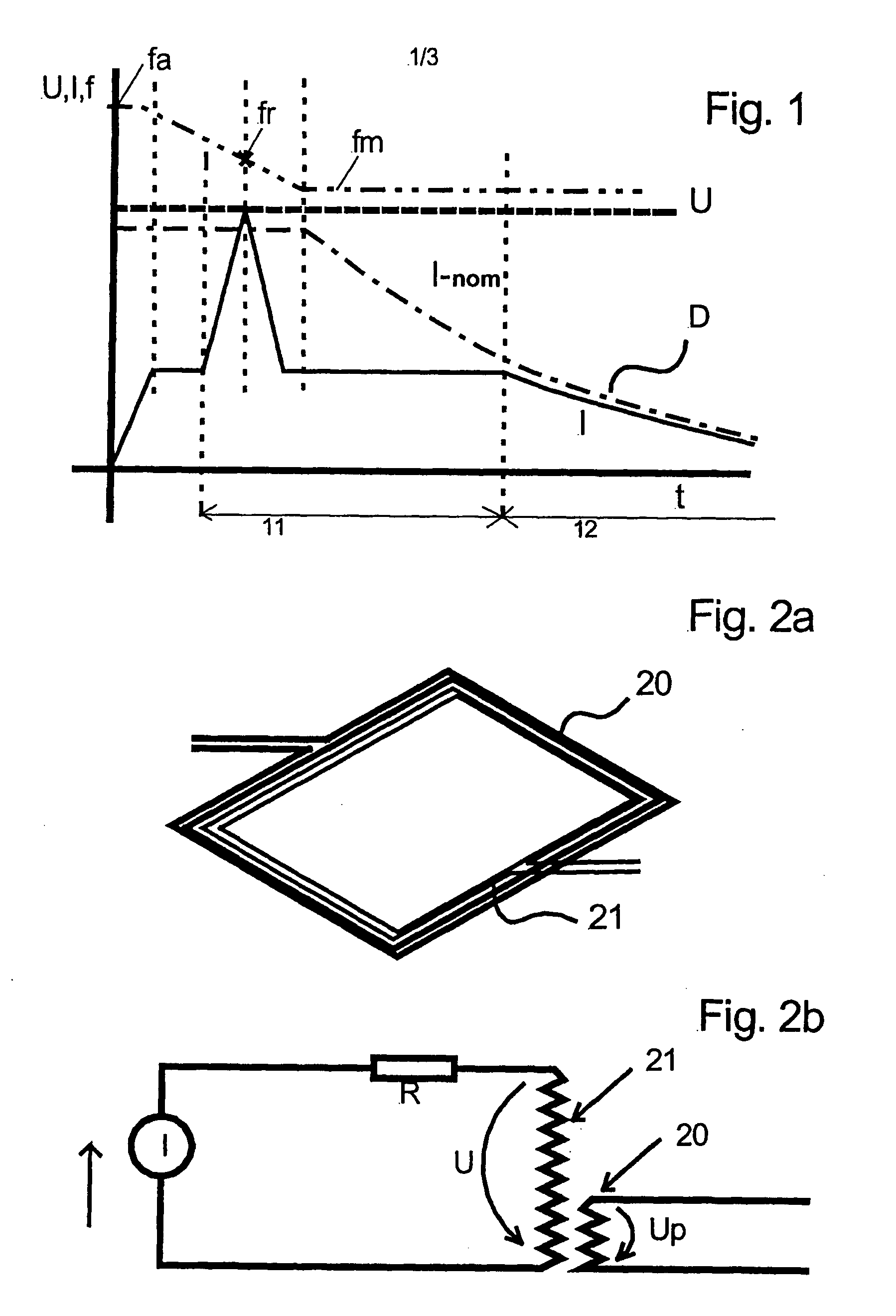
[0021] The course of the current I during the time t is represented in FIG. 1, according to the method according to DE 30 05 927 A1. The current course I is set against the optimal current course I-nom. In a first time interval 11, the demagnetization is effected in an uncontrolled manner on traveling through the resonant point at any location 12. A controlled demagnetization is effected with a controlled current only in the region of the second time interval. The decay of the curve D is only controlled and thus reproducible in the part section 12. The frequency is reduced from a high initial frequency fa to a demagnetisation frequency fm. Thereby, the resonant frequency fr is reached at some point therebetween.

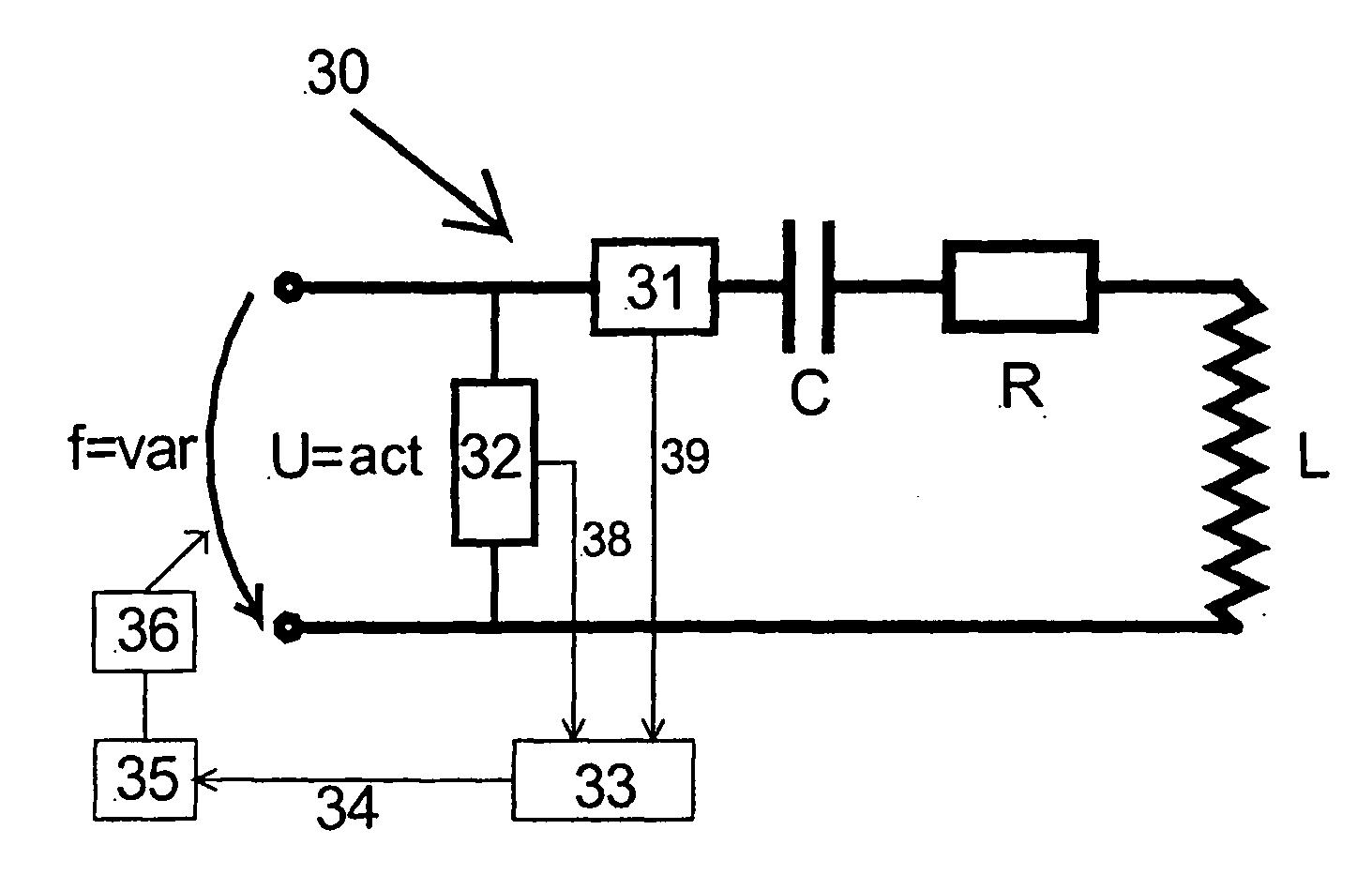
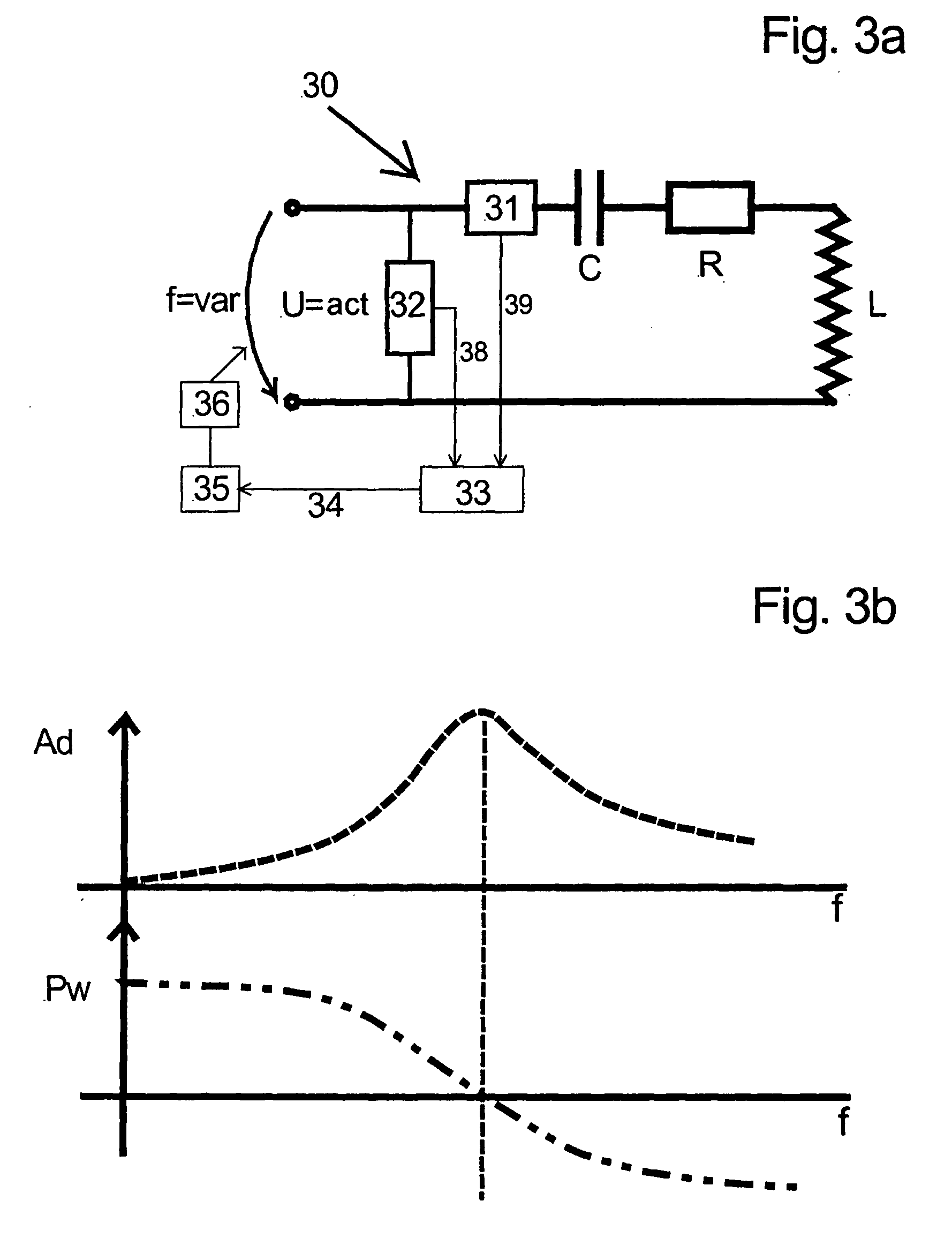
[0022] An alternative procedure according to FIG. 2a operates with an auxiliary coil or a low cross section, which determines the admittance of the auxiliary coil 21, and thus the inductance of the demagnetisation coil 20, and after further conversion, the corresponding reso...


PUM


Abstract

For demagnetizing larger parts and charges, from about 1 kg mass, the wattless power of the demagnetization coil is so high that it is compensated with a capacitor. The capacitor for this is connected in series with the coil, and a pulse-width-modulated inverter of the usual construction type is applied for the supply. The demagnetization may be effected by impulse or by running through a magnetic field of a constant strength. The inverter in the first case produces a current impulse of a certain frequency, shape and duration. In the second case, it produces a certain constant current at a certain frequency. In order with a given exit voltage of the inverter to achieve the highest possible current in the coil, the produced frequency must correspond to the resonant frequency of the oscillation circuit. In order to ascertain the resonant frequency of the charged coil, this may be measured by way of a separate measurement coil with a small measurement current. Afterwards, the frequency in the oscillation circuit is set to this value for the demagnetisation procedure.

Description


Claims


Application Information

Patent Timeline
Owner MAURER ALBERT
Why Eureka
Try Eureka