Instrumentation for the preparation and transplantation of osteochondral allografts

a technology for osteochondral allografts and instruments, which is applied in the field of instruments for the preparation and transplantation of osteochondral allografts, can solve the problems of difficult physical attachment and securing of allograft plugs to the recipient site, cartilage damage, and difficulty in repairing cartilage damag

Active Publication Date: 2007-06-14
BIOMET MFG CORP
View PDF99 Cites 47 Cited by
  • Summary
  • Abstract
  • Description
  • Claims
  • Application Information

AI Technical Summary

Benefits of technology

[0009] The invention provides one or more of the following advantages: An advantage of the invention is that it provides a osteochondral allograft plug that has a reduced amount of cancellous tissue and is therefore less likely to be rejected by a recipient. Another advantage is that it provides a specially shaped osteochondral allograft plug that can be fit and anchored into a correspondingly shaped cutout at the recipient site. These and other advantages and features of the invention will be apparent from the detailed description and the accompanying drawings.
is that it provides a osteochondral allograft plug that has a reduced amount of cancellous tissue and is therefore less likely to be rejected by a recipient. Another advantage is that it provides a specially shaped osteochondral allograft plug that can be fit and anchored into a correspondingly shaped cutout at the recipient site. These and other advantages and features of the invention will be apparent from the detailed description and the accompanying drawings.

Problems solved by technology

However, defects may develop in the cartilage from various causes such as abrupt trauma or prolonged wear.
One problem that arises with osteochondral allografts is that the recipient may adversely respond or reject the allograft plug.
In addition, physically attaching and securing the allograft plug to the recipient site presents difficulties.

Method used


Image

  • Instrumentation for the preparation and transplantation of osteochondral allografts
  • Instrumentation for the preparation and transplantation of osteochondral allografts
  • Instrumentation for the preparation and transplantation of osteochondral allografts

Examples


Embodiment Construction

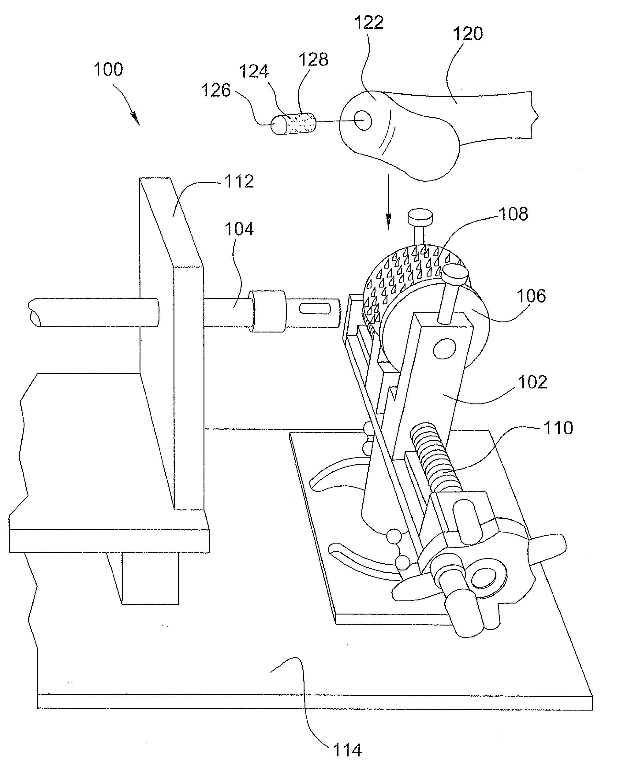
[0032] Now referring to the drawings, wherein like reference numbers refer to like elements, there is illustrated various processes and instruments for preparing and transplanting an osteochondral allograft in accordance with the various embodiments of the invention. Referring first to FIG. 1, there is shown a device 100 suitable for cutting and forming a cylindrically shaped allograft plug 124 from a donor bone 120 in accordance with one aspect of the invention. The device 100 itself includes a clamp assembly 102 and a tubular crown saw 104. The clamp assembly 102 includes two vertically extending clamp pads 106, 108, that can be moved with respect to each other by rotation of a linear screw mechanism 110. The crown saw 104 is directed towards and linearly movable with respect to the clamp assembly 102. To align the clamp assembly 102 and crown saw 104, the crown saw can pass through a vertical alignment plate 112 joined to a base 114 onto which the clamp assembly is also mounted. ...


PUM


Abstract

Provided are procedures and instruments for preparing and transplanting osteochondral allograft plugs to a host bone to repair an articular cartilage defect. An allograft bone plug having a cartilage plate and cancellous bone tissue attached thereto is removed from a donor bone. The allograft plug is further shaped by removing or cutting away cancellous bone tissue to form a cancellous stalk extending from the cartilage plate. The formed cancellous stalk can have any suitable shape including cylindrical, conical, and rectilinear. At the recipient site of the host bone, a cutout is formed corresponding in shape to the allograft plug. The allograft plug is inserted into the cutout such that the cancellous stalk is retained in the host bone and the cartilage plate aligns with the condyle surface of the host bone. Aspects of the invention may also be applicable to preparing and transplanting osteochondral autograft plugs.

Description

CROSS-REFERENCE TO RELATED APPLICATIONS [0001] This patent application is a divisional application of copending U.S. patent application Ser. No. 11 / 259,749, filed Oct. 26, 2005, the disclosure of which is herein incorporated by reference in its entirety.BACKGROUND OF THE INVENTION [0002] In humans and many other animals, cartilage is present on the surface of bones that form articular joints to facilitate articulation of the joint and protect and cushion the bones. However, defects may develop in the cartilage from various causes such as abrupt trauma or prolonged wear. A number of techniques have been attempted to treat such cartilage defects. One such technique is the transplantation of fresh osteochondral allografts. [0003] In this procedure, an allograft plug, also known as a osteochondral plug or core, is harvested from a condyle or rounded joint-forming portion of a donor bone. Intact on the surface of the allograft plug, on a portion of the bone known as the cartilage plate, ...

Claims


Application Information

Patent Timeline
Patent Type & Authority Applications(United States)
IPC IPC(8): A61F2/28
CPCA61B17/06166A61F2230/0093A61B17/1615A61B17/1675A61B17/282A61B2017/2837A61B2017/922A61F2/28A61F2/30756A61F2/3859A61F2/4601A61F2/4618A61F2/4644A61F2002/2839A61F2002/30113A61F2002/30153A61F2002/30156A61F2002/3021A61F2002/30233A61F2002/30273A61F2002/30275A61F2002/30299A61F2002/30764A61F2002/30772A61F2002/30971A61F2002/4649A61F2002/4681A61F2230/0006A61F2230/0019A61F2230/0023A61F2230/0067A61F2230/0069A61F2230/0086A61F2230/0089A61B17/1604
Inventor MALININ, THEODORE I.
Owner BIOMET MFG CORP
Why Eureka
Try Eureka