Channel emulating device

Inactive Publication Date: 2007-06-14
ACCTON TECHNOLOGY CORPORATION
View PDF5 Cites 7 Cited by
  • Summary
  • Abstract
  • Description
  • Claims
  • Application Information

AI Technical Summary

Benefits of technology

[0010] As mentioned above, a channel emulating device according to the present invention utilizes the choosing modules, the signal integrating modules and the parameter adjusting modules to produce a plurality of channels and gain parameters between the testing device and the device-und

Problems solved by technology

Consequently, the system will be very huge and com

Method used


Image

  • Channel emulating device
  • Channel emulating device
  • Channel emulating device

Examples


Example

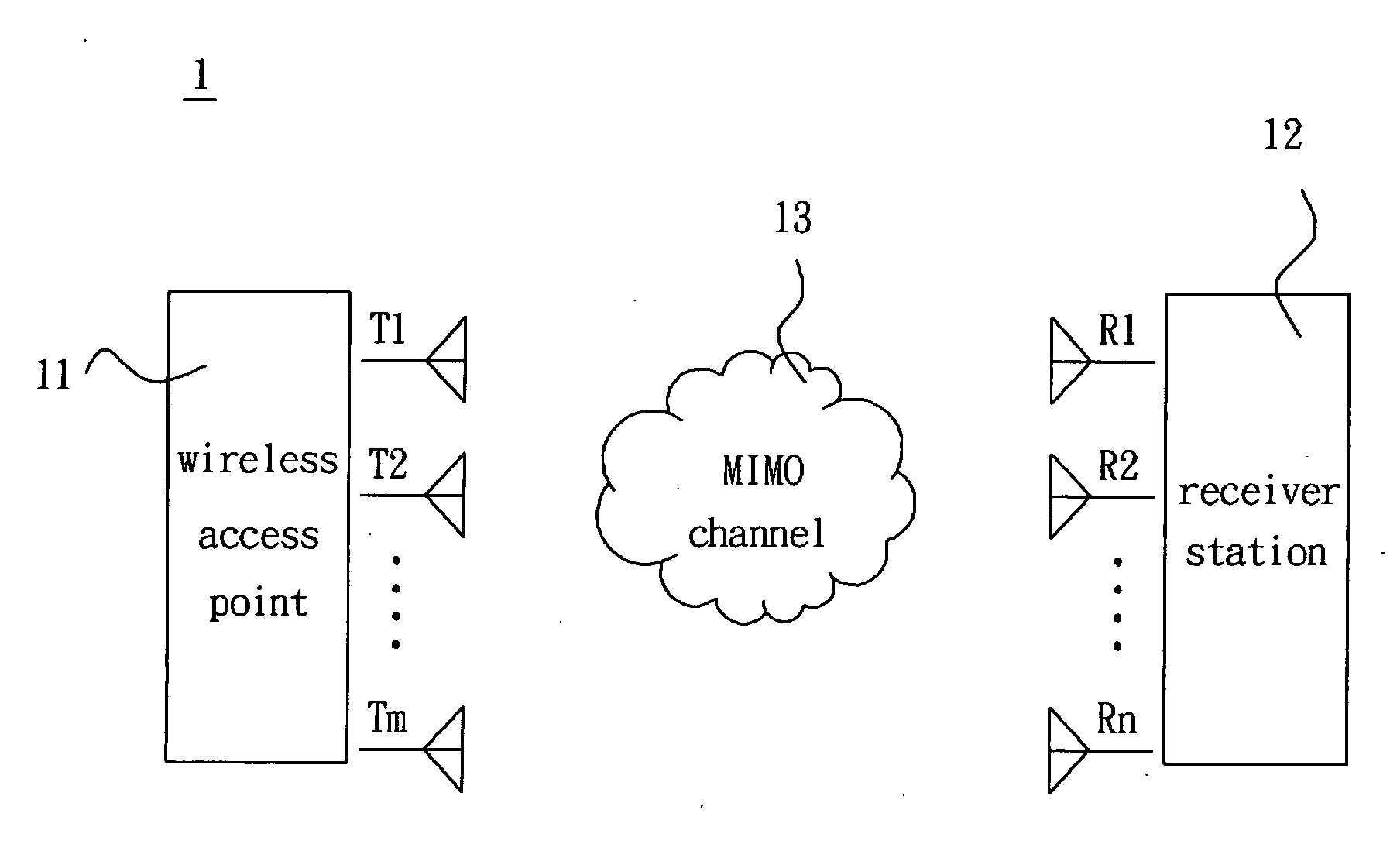
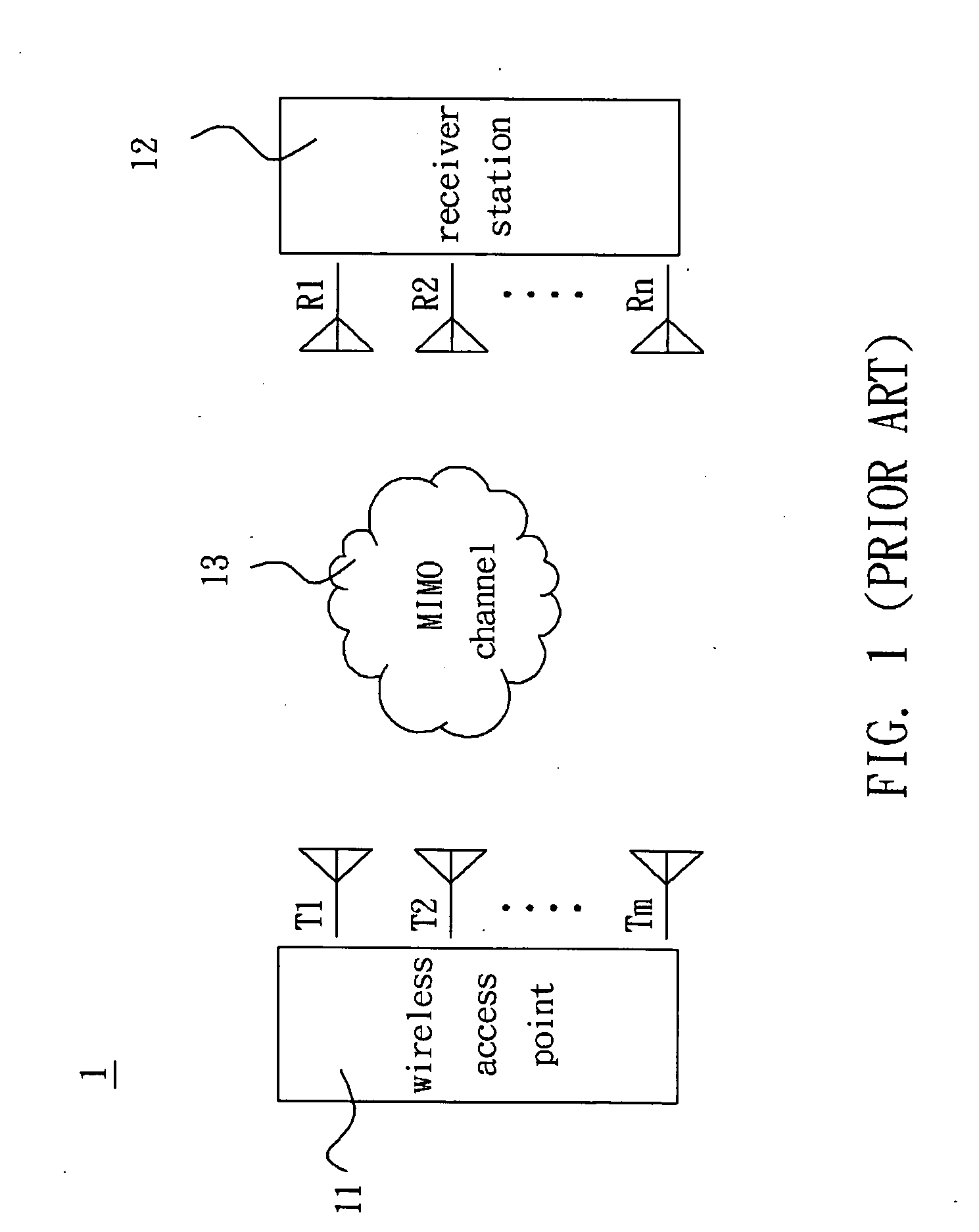
[0018] As shown in FIG. 3, a channel emulating device according to a first embodiment of the present invention emulates such as 4×4 wireless transmission systems.

[0019] In this embodiment, the channel emulating device 5 is disposed between a testing device TD and a device-under-test DUT. The testing device TD has a wireless access point (AP)(not shown). The testing device TD generates a first input signal S1 and three second input signals S2, S3 and S4 and transmits the signals S1 to S4 to the channel emulating device 5. The device-under-test DUT has an Ethernet adapter and a computer (not shown). The device-under-test DUT receives a first output signal X1 and three second output signals X2, X3 and X4. The channel emulating device 5 includes a first choosing module 51, a first signal integrating module 52, a first parameter adjusting module 53, a second parameter adjusting module 54, a second choosing module 55, a second signal integrating module 56 and a third choosing module 57. ...

Example

[0037] As shown in FIG. 4, a channel emulating device according to a second embodiment of the present invention emulates such as 2×2 wireless transmission systems.

[0038] In this embodiment, the channel emulating device 6 is disposed between a testing device TD and a device-under-test DUT. The testing device TD generates a first input signal S1 and a second input signal S2 and transmits the signals S1 and S2 to the channel emulating device 6. The device-under-test DUT receives a first output signal X1 and a second output signal X2. The channel emulating device 6 includes a first choosing module 61, a first signal integrating module 62, a first parameter adjusting module 63, a second parameter adjusting module 64, a second choosing module 65, a second signal integrating module 66, a third choosing module 67 and a control module 68. The connections, properties and functions of the above-mentioned modules are the same as those of the first embodiment, and detailed descriptions thereof ...


PUM


Abstract

A channel emulating device includes a first choosing module, a first signal integrating module, a first parameter adjusting module, a second choosing module, a second signal integrating module, a second parameter adjusting module and a third choosing module. The first signal integrating module generates at least one first integrated signal in accordance with a first input signal and at least one second input signal. The first and the second parameter adjusting modules respectively generate at least one first parameter signal and at least one second parameter signal. The second signal integrating module generates a plurality of second integrated signals in accordance with the first parameter signal and the second parameter signal. One of the second integrated signals acts as a first output signal. The third choosing module receives the second parameter signal and outputs the second parameter signal through a fifth channel or receives the rest of the second integrated signals and outputs the rest of the second integrated signals through a sixth channel to act as at least one second output signal.

Description

BACKGROUND OF THE INVENTION [0001] 1. Field of Invention [0002] The present invention relates to an emulating device, and more particularly, to a channel emulating device adapted to multiple-input multiple-output (MIMO) transmission systems. [0003] 2. Related Art [0004] Accompanying to the progress of the technology, the wireless transmission-technology has been continuously developed and has tightly combined with the daily life. The electronic products such as mobile phones, personal digital assistants (PDAs), personal computers, and the like have brought a more convenient environment. In the age of the mass information flow, the demand on the-wireless transmission gets higher and higher. [0005] A wireless communication system having a higher efficiency and a higher capability are needed in order to enhance the information transmission quality and the signal covering range and to implement the reliable and stable transmission. A MIMO transmission system is one of the wireless commu...

Claims


Application Information

Patent Timeline
IPC IPC(8): G06F9/455
CPCH04B17/0087H04B17/3912H04L41/145
Inventor LIU, I-RU
Owner ACCTON TECHNOLOGY CORPORATION
Why Eureka
Try Eureka