Perpendicular magnetic recording write head with enhancement capacitor on slider body for write current overshoot at write current switching

Active Publication Date: 2011-05-12
WESTERN DIGITAL TECH INC
View PDF15 Cites 6 Cited by
  • Summary
  • Abstract
  • Description
  • Claims
  • Application Information

AI Technical Summary

Benefits of technology

[0008]The first and second terminals on the head carrier are adapted for connection to a write driver that has a voltage VD and resistance RWD for supplying a write current to the write head, wherein the write head has an inductance LH and resistance RH. With the write enhancement circuitry on the head carrier, the write head has a write current response with an attenuation constant α=1/[2(RWD+RE)CE]. Proper selectio

Problems solved by technology

However, the switching time for the write pole of the write head to switch from one ma

Method used


Image

  • Perpendicular magnetic recording write head with enhancement capacitor on slider body for write current overshoot at write current switching
  • Perpendicular magnetic recording write head with enhancement capacitor on slider body for write current overshoot at write current switching
  • Perpendicular magnetic recording write head with enhancement capacitor on slider body for write current overshoot at write current switching

Examples


Example

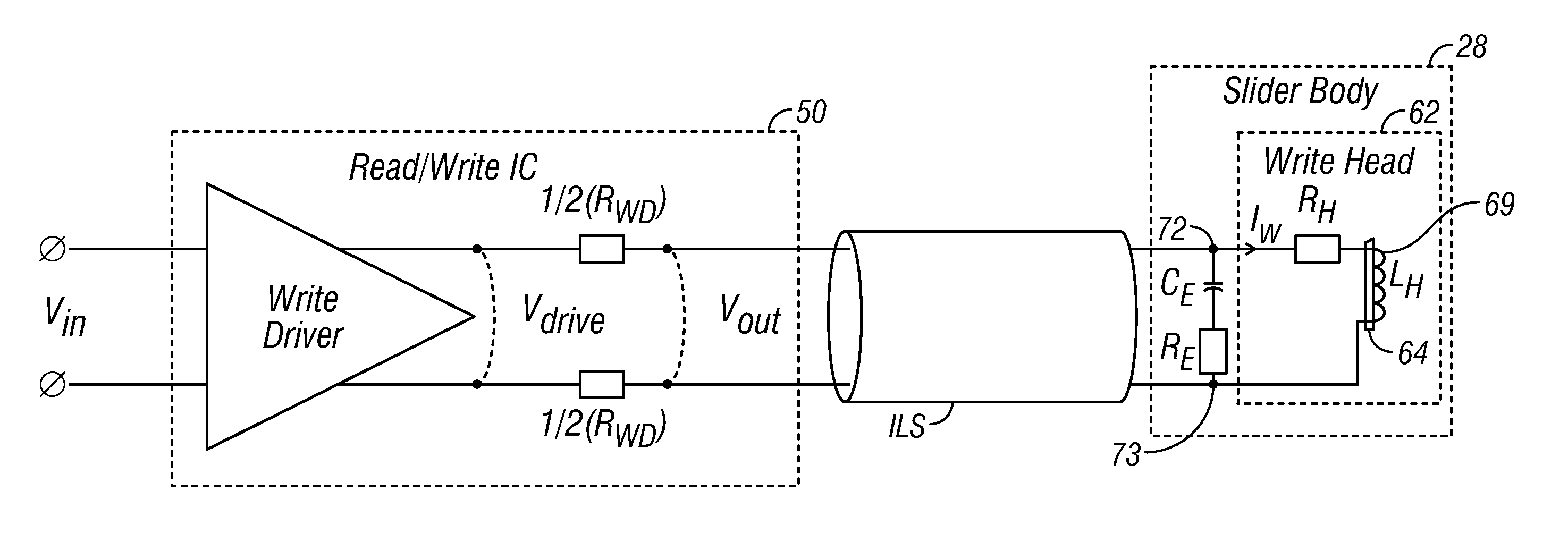
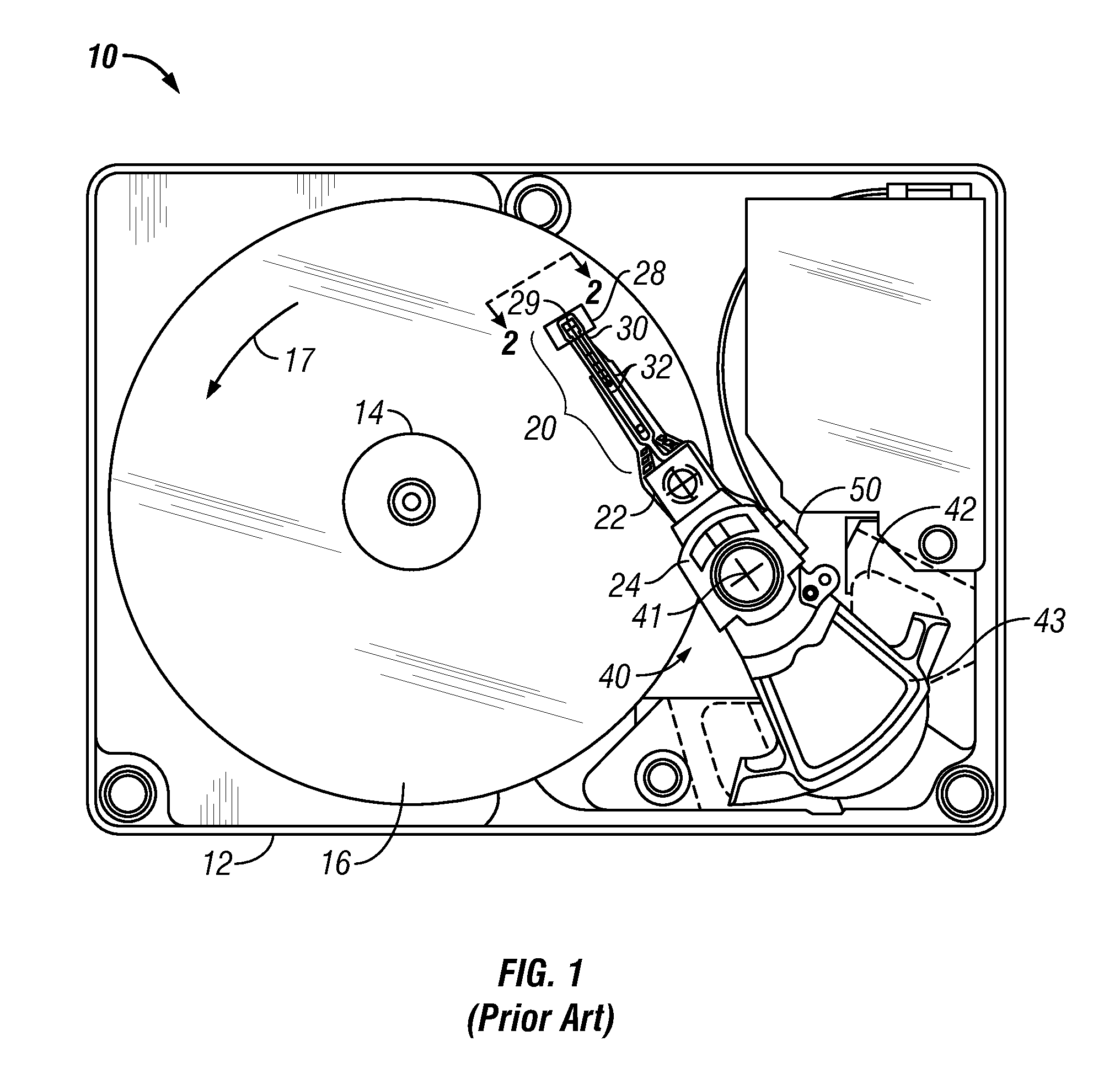
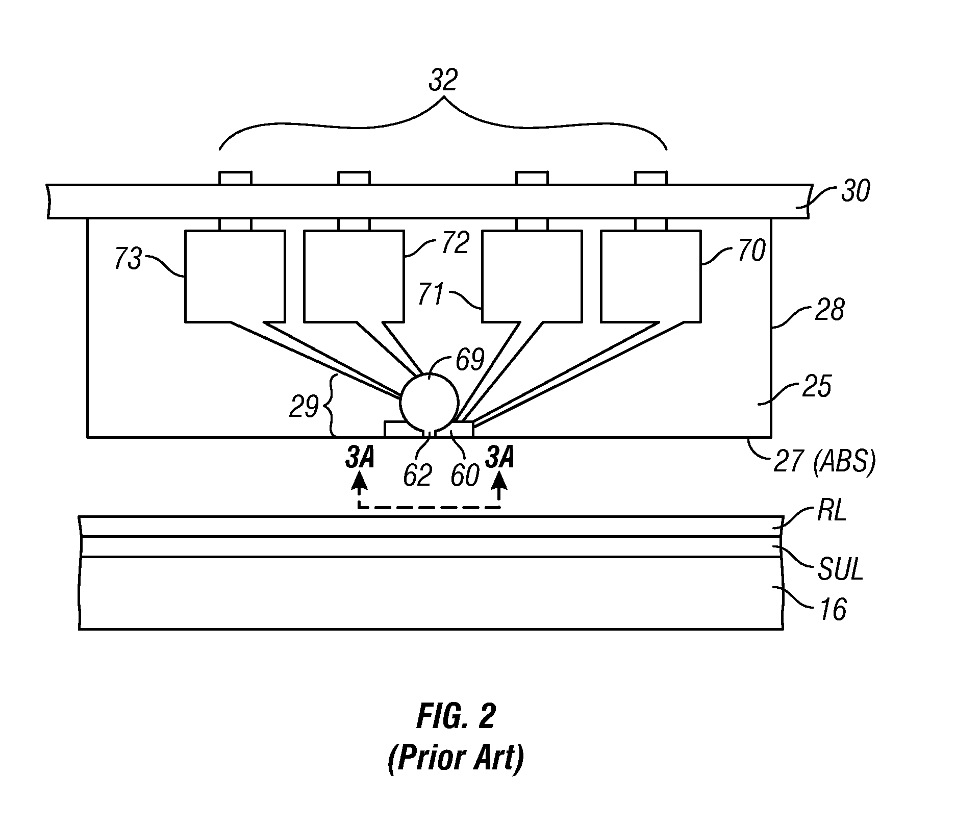
[0018]FIG. 1 is a top plan view of a head / disk assembly of a hard disk drive 10 like that for use with the present invention with the cover removed. The disk drive 10 includes a rigid base 12 supporting a spindle 14 that supports a stack of disks, including top disk 16. The spindle 14 is rotated by a spindle motor (not shown) for rotating the disks in the direction shown by curved arrow 17. The hard disk drive 10 has at least one load beam assembly 20 having an integrated lead suspension (ILS) or flexure 30 with an array 32 of electrically conductive interconnect traces or lines. The load beam assemblies 20 are attached to rigid arms 22 connected to an E-shaped support structure, sometimes called an E-block 24. Each flexure 30 is attached to a head carrier, for example an air-bearing slider 28. A magnetic recording read / write head 29 is located at the end or trailing surface 25 of slider 28. The flexure 30 enables the slider 28 to “pitch” and “roll” on an air-bearing generated by th...


PUM


Abstract

Write enhancement circuitry on the head carrier of a magnetic recording disk drive provides additional write current overshoot beyond that provided by the write driver circuitry. An enhancement capacitor is formed with a dielectric layer between two layers of electrically-conductive magnetically-permeable shield material that serve as the capacitor plates. The write enhancement circuitry may also include an enhancement resistor. The enhancement capacitor and resistor are connected between the two terminals on the head carrier that connect to the write head coil. The capacitor and resistor are fabricated on the head carrier at the same time and in the same process as the read head. The first and second capacitor plates are generally coplanar with and formed of the same electrically-conductive magnetically-permeable material that forms the first and second magnetic shields for the read head. The enhancement resistor is a stack of layers that is coplanar with and formed of the same materials as the stack of layers that form the sensor portion of the read head between the two magnetic shields.

Description

BACKGROUND OF THE INVENTION[0001]1. Field of the Invention[0002]This invention relates generally to perpendicular magnetic recording systems, and more particularly to a system with fast switching of the magnetization direction of the perpendicular write head.[0003]2. Description of the Related Art[0004]Perpendicular magnetic recording, wherein the recorded bits are stored in a perpendicular or out-of-plane orientation in the recording layer, allows for ultra-high recording densities in magnetic recording hard disk drives. The write head must be able to write data not only at high bit-density but also at high data-rates. The write speed is particularly important in enterprise disk drives. However, the switching time for the write pole of the write head to switch from one magnetization direction to the other is a limiting factor as the data rate is increased. At high data-rates, the available magnetic flux from the write head, as seen by the recording layer on the disk, is limited by ...

Claims


Application Information

Patent Timeline
IPC IPC(8): G11B5/17
CPCG11B5/09G11B5/3116G11B5/1278
Inventor CONTRERAS, JOHN THOMASSEAGLE, DAVID JOHN
Owner WESTERN DIGITAL TECH INC
Why Eureka
Try Eureka