
Staircase block and staircase construction method using the staircase block

Inactive Publication Date: 2007-06-21
TADA KIMIO
View PDF11 Cites 1 Cited by
  • Summary
  • Abstract
  • Description
  • Claims
  • Application Information

AI Technical Summary

Benefits of technology

[0013] According to the present invention, the weight of the staircase block of 330 mm length is approximately 26 kg per block, which is movable enough by hands. The manual portability of the blocks is a big advantage in the situation of a inclined land where any heavy construction machines are hard to be utilized.
[0014] Because of the round parts (partially cylindrical recess surface) formed at the inner corner parts of the recess in the rear surface of the block, the mortar laid under the block leaves no unfilled vacancy, and therefore, residual air and moisture which cause expansion breakage are in hot or cold time are effectively excluded.
[0015] Weight reduction effect is increased by forming a large recess in the rise surface of the block. And, by filling mortar in the displacement prevention grooves formed on the side surfaces of the block and placing the side surface to another, a displacement prevention an effect is produced as if adjacent blocks are tied by a wedge.

Problems solved by technology

This strain causes cracks on the surface of the mortar, through which water can penetrate.
Further, a slight amount of air and moisture caught under the mortar layer can cause it to be fallen off the steps because of repeated expansion of air at high temperature and of frozen water at low temperature.
For the above mentioned reasons, the conventional constructing method is not suited to cold regions where land freezes and the time when temperature difference is extremely large.
However, a cavity in the mortar filled in the inner space of the L shaped staircase block can be produced due to insufficient filling at the corner of the block or at the joint between blocks.
Expansion of air and water in the cavity is apt to cause the problem of peeling between the blocks.
However, on the basis of the conventional constructing method, it has been difficult to satisfy such requirements, due to various difficulties in the execution of works.
However, in the prior art, such problems have undergone as that the proposed staircase block is too heavy to be handled manually, that the neighbouring blocks shift from the right position, and that a undesirable space which causes separation of the rear surface of the staircase block from the ground concrete due to air layer is likely to occur.

Method used


Image

  • Staircase block and staircase construction method using the staircase block
  • Staircase block and staircase construction method using the staircase block
  • Staircase block and staircase construction method using the staircase block

Examples


examples

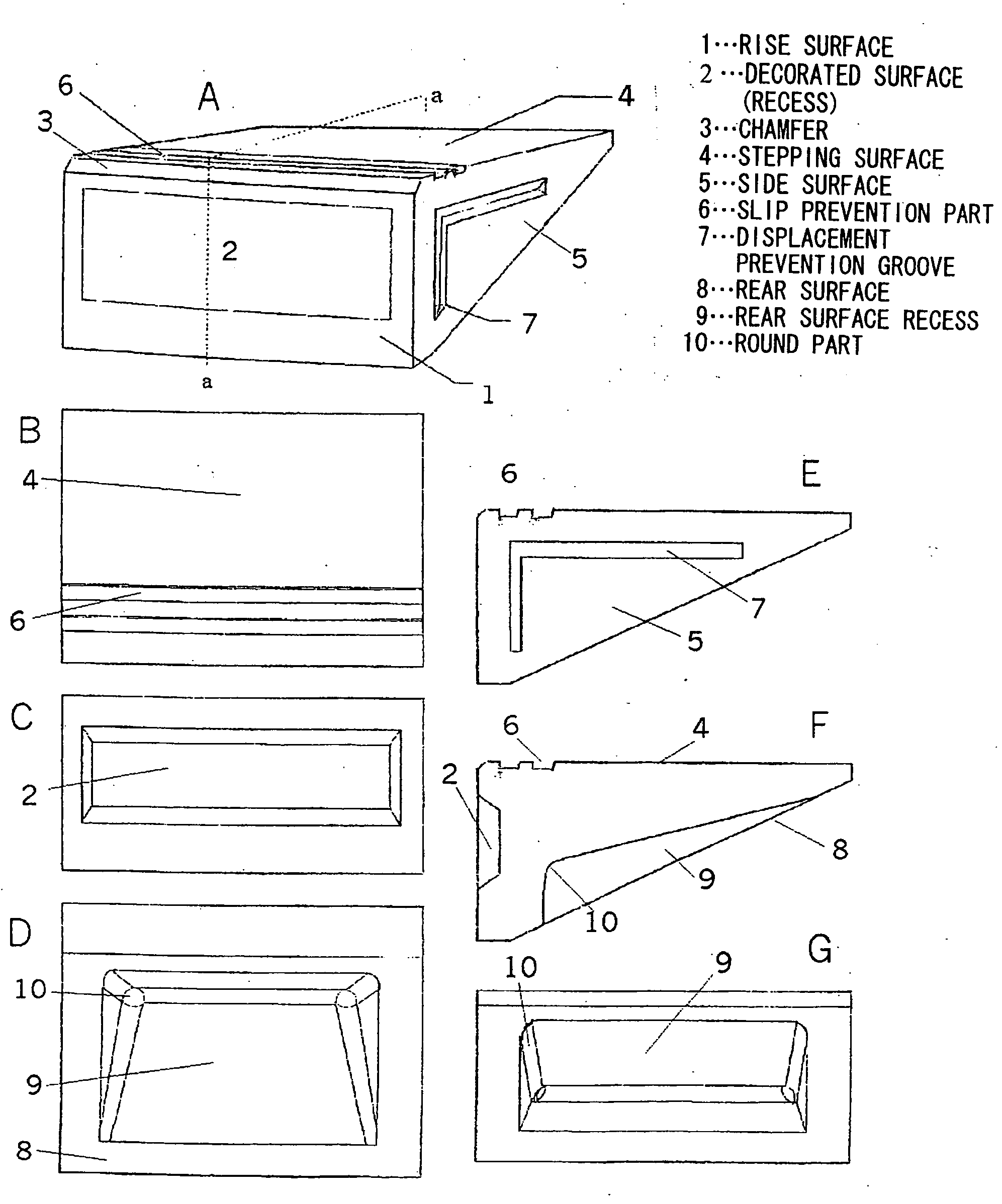
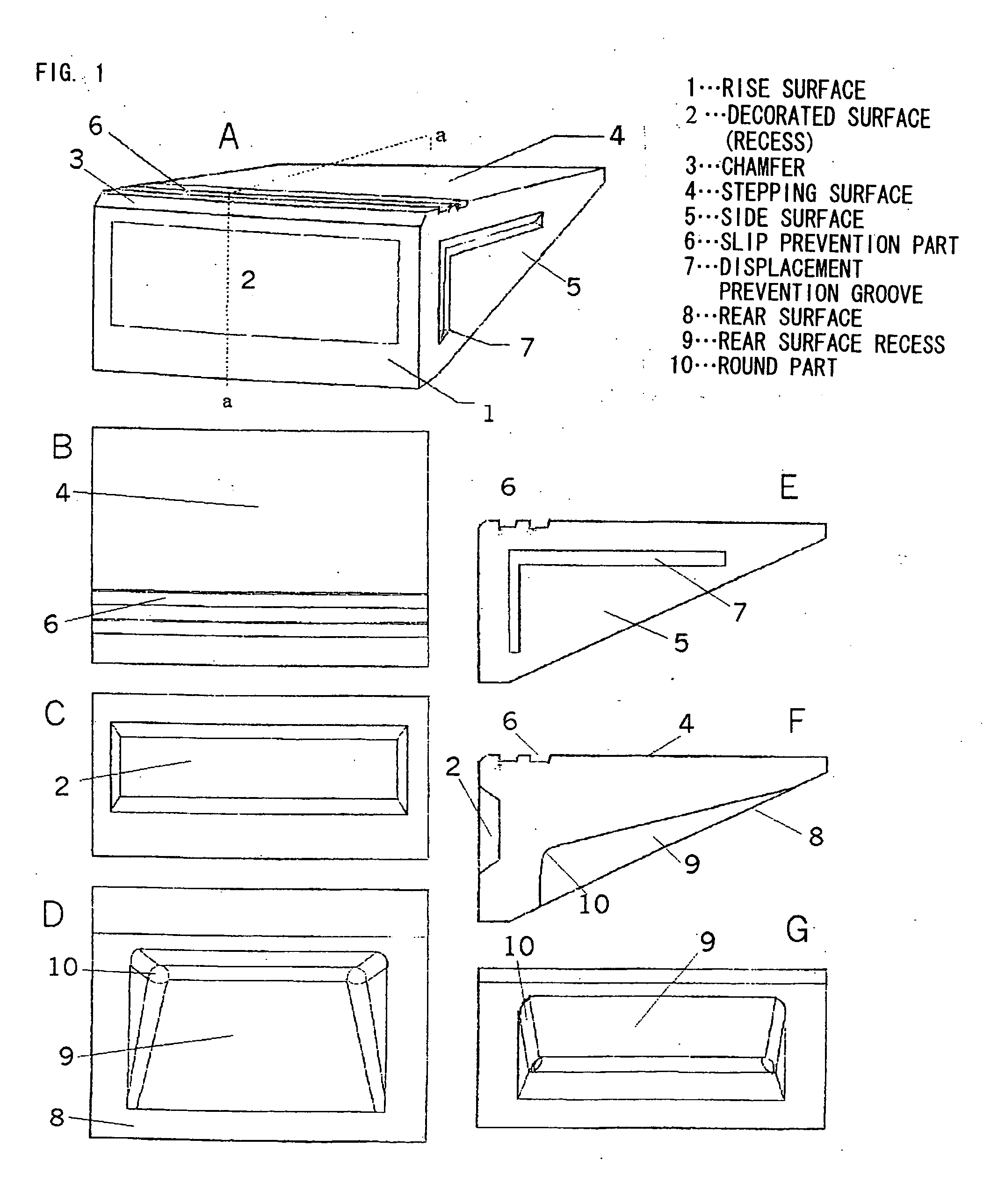
[0025]FIG. 1 shows a perspective view, a plan, a front view, a rear view, a side view, a sectional view, and a back-side view of the staircase block as an example of the present invention. In FIG. 1, FIG. 1A is the perspective view, B is the plan, C is the front view, D is the rear view, E is the side view, F is the sectional view, and G is the back-side view of the staircase block.

[0026] A reference sign 1 shown in FIG. 1 represents a rise surface, 2 a recess in the middle of the rise surface, 3 a chamfer between a stepping surface and the rise surface, 4 the stepping surface, 5 a side surface, 6 slip prevention grooves, 7 displacement prevention grooves, 8 a back-side surface, 9 a recess in the back-side surface, and 10 round parts in the back-side recess.

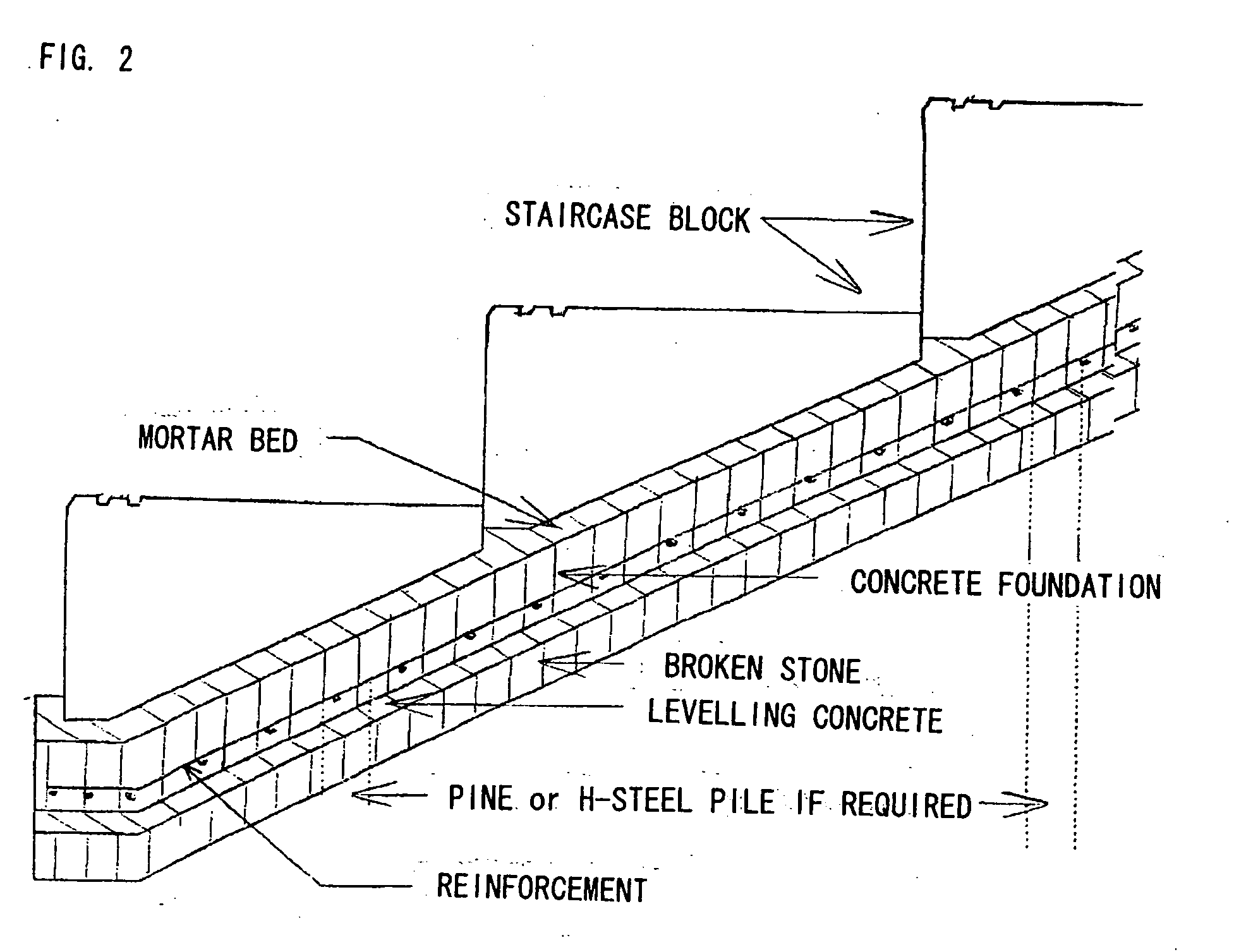
[0027]FIG. 2 is a sectional view showing a total structure of a staircase constructed using the staircase block shown in FIG. 1. Mortar is laid on a foundation of concrete with reinforcement, and the staircase blocks are arrang...


PUM


Abstract

To reduce the weight of a staircase block so as to be manually carried and installed, prevent adjacent blocks from being displaced from each other after installation, and prevent the blocks from being raised and separated from each other due to heating and cooling by conquering problems with the staircase blocks related to publicly known technologies. In this precast concrete block for building a staircase, large recesses (2) and (9) are formed in the rise surface (1) and the rear surface (8) of the block to reduce the weight, and displacement prevention grooves (7) for connecting the adjacent blocks to each other with mortar are formed in the side faces of the block, and round parts (partially cylindrical recessed surfaces) (10) with a specified radius are formed at the inner corner parts of the recess (9) in the rear surface so that an acute angle part preventing the adhesive mortar from being filled therein is not produced.

Description

FIELD OF INVENTION [0001] The present invention relates to a pre-cast concrete staircase block used for constructing a staircase in a construction site, and a staircase construction method using the staircase block. BACKGROUND OF INVENTION [0002] A staircase in a residential area has conventionally been constructed as follows: Firstly, a face of inclined land is evenly tamped, foundation concrete with reinforcement is placed on the slope, steps of the staircase are roughly formed of concrete on the foundation, and finally, faces of the roughly-formed steps are mortar finished (FIG. 4). [0003] In the staircase built by the above conventional method, strain is often created between the roughly-formed steps and the face mortar layer, as the rate of expansion and contraction of both materials against temperature change or humidity change differ from each other. This strain causes cracks on the surface of the mortar, through which water can penetrate. Further, a slight amount of air and ...

Claims


Application Information

Patent Timeline
IPC IPC(8): E04B1/00E02D17/20E04F11/02E04F11/116
CPCE04F11/02E04F2011/0212E04F11/116E04C1/00E02B3/14
Inventor TADA, KIMIO
Owner TADA KIMIO
Learn More