Feed source device capable of realizing antenna C/Ku band switching and method thereof

A C-band and ku-band technology is applied in the field of antenna feed conversion devices, which can solve problems such as difficulties, many restrictive factors, antenna gain, and adverse effects of standing wave characteristics and cross-polarization isolation, so as to avoid the inconvenience of carrying, The effect of improving work efficiency and increasing difficulty

Active Publication Date: 2014-09-03
NANJING CHINA SPACENET SATELLITE TELECOM
View PDF4 Cites 0 Cited by
  • Summary
  • Abstract
  • Description
  • Claims
  • Application Information

AI Technical Summary

Problems solved by technology

At present, there are two ways to solve this problem: one way is to use two antennas, one antenna receives the C-band signal, and the other antenna receives the Ku-band signal. It is inconvenient to carry, install, and use the satellite; another way is to process and integrate the feed speakers of C-band and Ku-band into one feed speaker to achieve the purpose of receiving C-band and Ku-band at the same time, but the Ku-band The working frequency band of the C-band is much larger than that of the C-band. It is difficult to design such a shared feed horn, there are many constraints, and it is difficult to select parameters. Moreover, the use of such a shared horn on the antenna will affect the gain of the antenna and the standing baud rate of the antenna. Sexuality and cross-polarization isolation have adverse effects

Method used


Image

  • Feed source device capable of realizing antenna C/Ku band switching and method thereof
  • Feed source device capable of realizing antenna C/Ku band switching and method thereof
  • Feed source device capable of realizing antenna C/Ku band switching and method thereof

Examples


Embodiment Construction

[0031] The accompanying drawings disclose non-restrictive structural schematic diagrams of the embodiments involved in the present invention, and the technical solution of the present invention will be described in detail below in conjunction with the accompanying drawings.

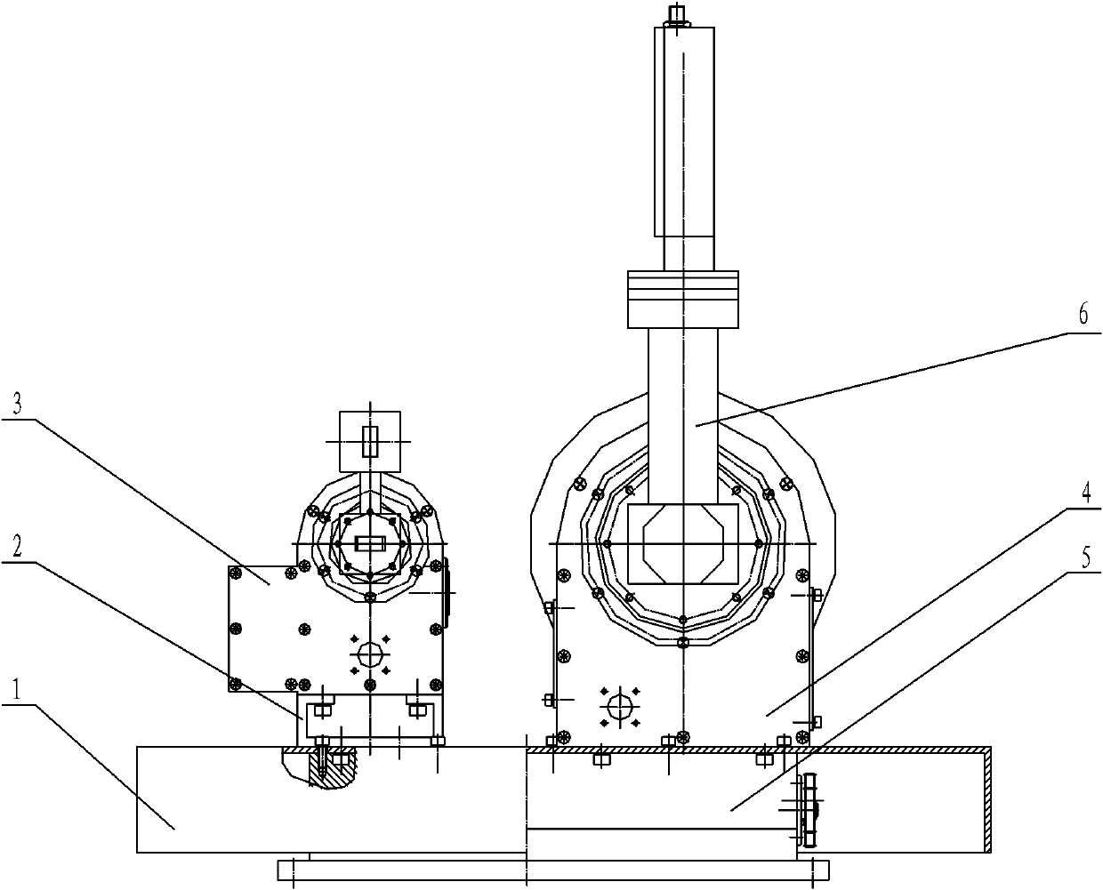
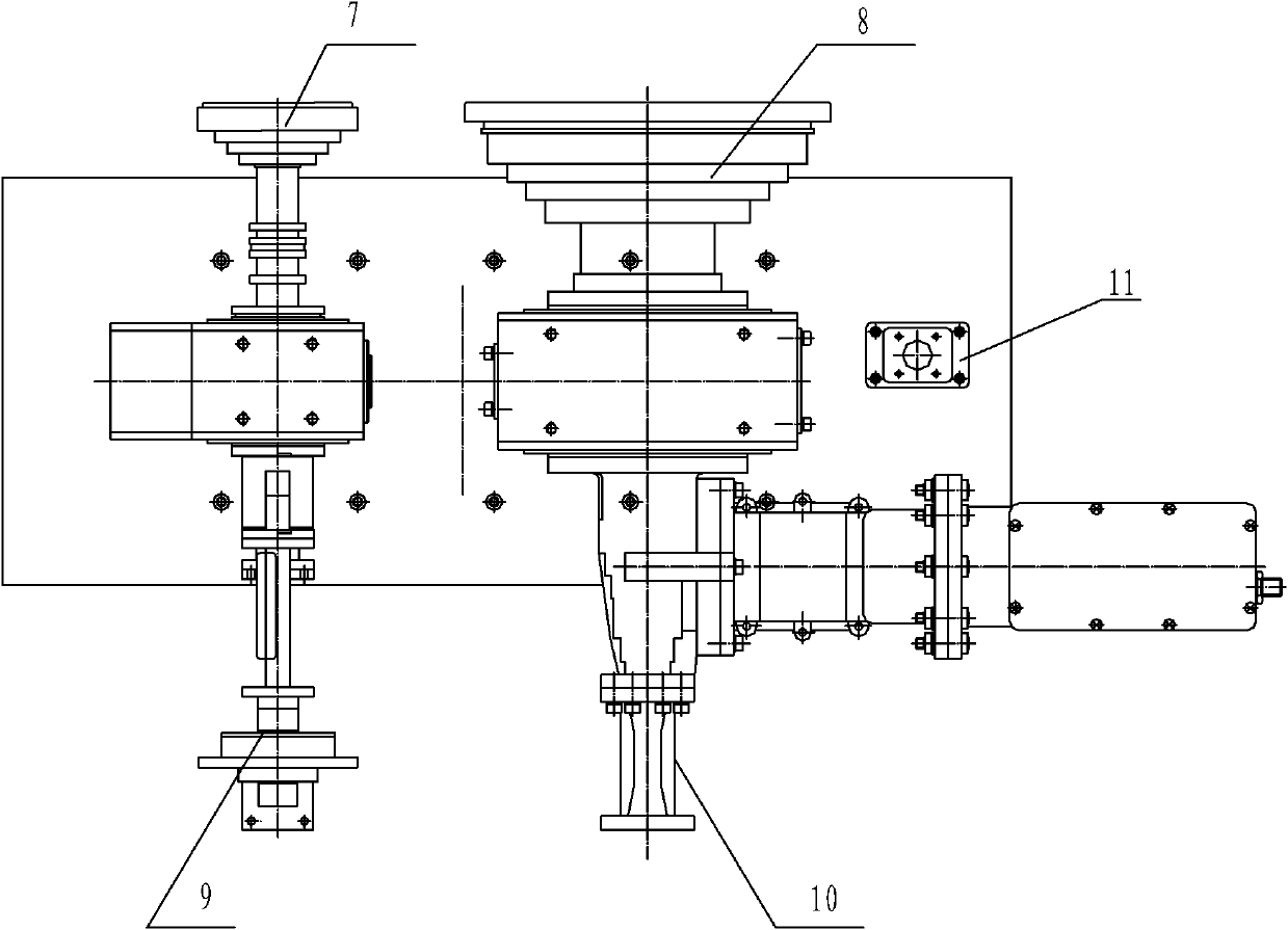
[0032] Such as figure 1 and figure 2 As shown, the feed device capable of realizing antenna C / Ku-band conversion according to the present invention includes a C-band feed 8, a Ku-band feed 7, a C-band feed rotation assembly 4, a Ku-band feed rotation assembly 3, and a C-band feed rotation assembly. The band feed tuner 6, the Ku band feed tuner, the Ku band feed waveguide connecting part 9, the C band feed waveguide connecting part 10 and the reciprocating linear moving guide rail 5, the C band feed rotating assembly 4 and The Ku-band feed rotating assembly 3 is installed on the reciprocating linear moving guide rail 5 at intervals through the shell 1, and the reflection focus of the antenna surface is l...


PUM


Abstract

The invention discloses a feed source device capable of realizing antenna C / Ku band switching and a method thereof. A C-band feed source and a Ku-band feed source are respectively arranged on a reciprocating linear motion guide rail by two corresponding rotary assemblies at intervals; at the same time, reflecting focal points on an antenna surface are projected between the C-band feed source and the Ku-band feed source; the C-band feed source or the Ku-band feed source receives the reflecting focal points on the antenna surface by the linear motion of the linear motion guide rail; and the direction of polarization of the C-band feed source or the Ku-band feed source is adjusted by the rotation of the corresponding rotary assembly. The feed source device is simple and compact in structure and convenient to use; the automation control is adopted to receive the switching of C-band signals and Ku-band signals and adjust polarizing angles; and the feed source device is convenient and practical, and has strong practical applicability in a satellite communication system.

Description

technical field [0001] The invention relates to an antenna feed source switching device and a method thereof, so that satellite signals of C band and Ku band can be exchanged and received on the same antenna. Background technique [0002] At present, with the continuous development of satellite communication, it has become a consensus to apply satellite communication technology to the field of emergency communication. In the satellite communication systems of various industries, the satellite communication frequency bands used are different, among which the C-band and Ku-band are commonly used satellite communication frequency bands. In actual communication services, sometimes it is necessary to be able to receive not only the C-band signal of a certain satellite resource, but also the Ku-band signal of a certain satellite resource. At present, there are two ways to solve this problem: one way is to use two antennas, one antenna receives the C-band signal, and the other ant...

Claims


Application Information

Patent Timeline
Patent Type & Authority Patents(China)
IPC IPC(8): H01Q13/02H01Q5/00H01Q5/50
Inventor 裘德龙王巧樑孙俊高云勇
Owner NANJING CHINA SPACENET SATELLITE TELECOM
Why Eureka
Try Eureka