Collapsible steering column device having telescopic mechanism

a technology of telescopic mechanism and collapsible steering column, which is applied in the direction of steering parts, pedestrian/occupant safety arrangement, vehicle components, etc., can solve the problems of difficult to reduce the electric resistance of this sliding portion, the steering column b>1/b> cannot be smoothly contacted by a desired intensity of impact load, and the difficulty in designing the collapsible steering column device for providing, etc. stably contracted, stable operation and high stability

Inactive Publication Date: 2007-06-21
NSK LTD +1
View PDF6 Cites 32 Cited by
  • Summary
  • Abstract
  • Description
  • Claims
  • Application Information

AI Technical Summary

Benefits of technology

[0032] Since the collapsible steering column device having a telescopic mechanism of the present invention is configured and operated as described above, a holding force of holding the inner column by the outer column can be stably maintained high, and further designing can be easily executed when various electronic parts provided in the steering wheel are connected to the earth. Further, without uselessly increasing the number of parts or strictly controlling the breaking strength of the stopper member, the steering column can be stably contracted by an impact load given at the time of the secondary collision.

Problems solved by technology

In the case of the first example of the conventional structure described above, when a sliding portion for smoothly contracting the steering column 1 is provided, it becomes difficult to design the collapsible steering column device for providing the earth of various electric parts such as a horn, which is attached to the steering wheel, in a portion electrically continued to a vehicle body.
For the above reasons, there is a possibility that the steering column 1 can not be smoothly contacted by a desired intensity of the impact load.
However, in this case, it is difficult to reduce electric resistance of this sliding portion.
Therefore, the following problems may be encountered in this case.
Accordingly, it becomes difficult to provide an electrical continuation route for making both the columns 3, 2 stably continue to each other.
Therefore, in the process of designing the collapsible steering column device, it becomes difficult to arrange the earth of various electronic parts such as a horn attached to the steering wheel in a portion which is electrically continued to an automobile body.
The first problem is that the pair of arm portions 7, 7 provided in the outer column 2, 2a can not stably hold the inner column 3.
However, in the case where the oscillating angle of the operation lever 12 is increased, it becomes complicated to adjust a position of the steering wheel.
In the case of increasing the wall thickness of the inner column 3, the weight of the device is uselessly increased.
It is difficult to stably contract the steering column by an impact load given at the time of the secondary collision without strictly controlling a breaking strength of some parts and without greatly increasing the number of parts.
However, in the structure in which the stopper member 14 or the bolt 17 is broken, it is difficult to strictly control a load (a breaking strength) needed for breaking the stopper member 14 or the bolt 17.
Therefore, it is difficult that the above contraction is stably executed by an impact load, the intensity of which is not less than a predetermined value.
In the case where another sliding member is slidably engaged with the inner and the outer column 3, 2, 2a, the number of parts is greatly increased, which uselessly increases the manufacturing cost.
However, even in the structure described in Patent Document 4, no consideration is given to a smooth contraction of the steering column after the contraction of the steering column has been restricted by the above protrusion.
However, the same problems as those described before are also caused.

Method used


Image

  • Collapsible steering column device having telescopic mechanism
  • Collapsible steering column device having telescopic mechanism
  • Collapsible steering column device having telescopic mechanism

Examples


embodiment 1

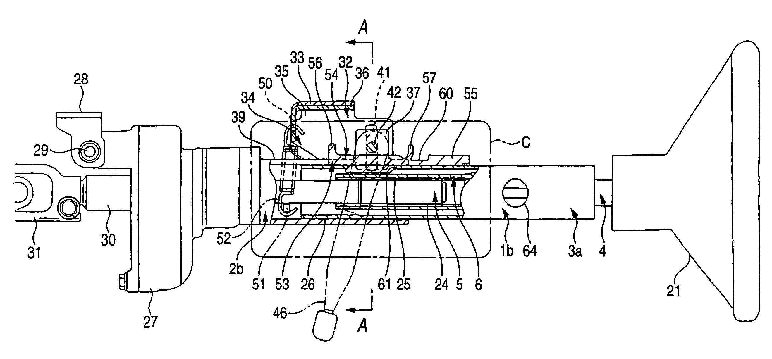
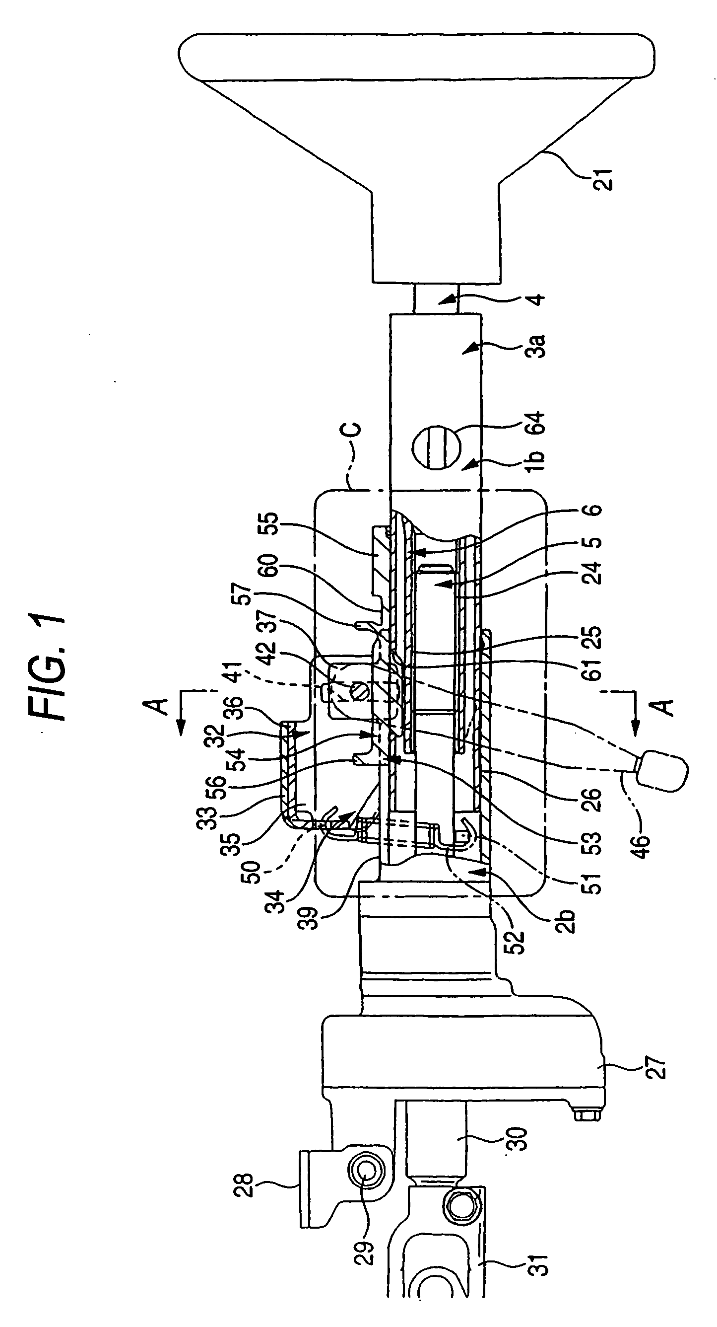
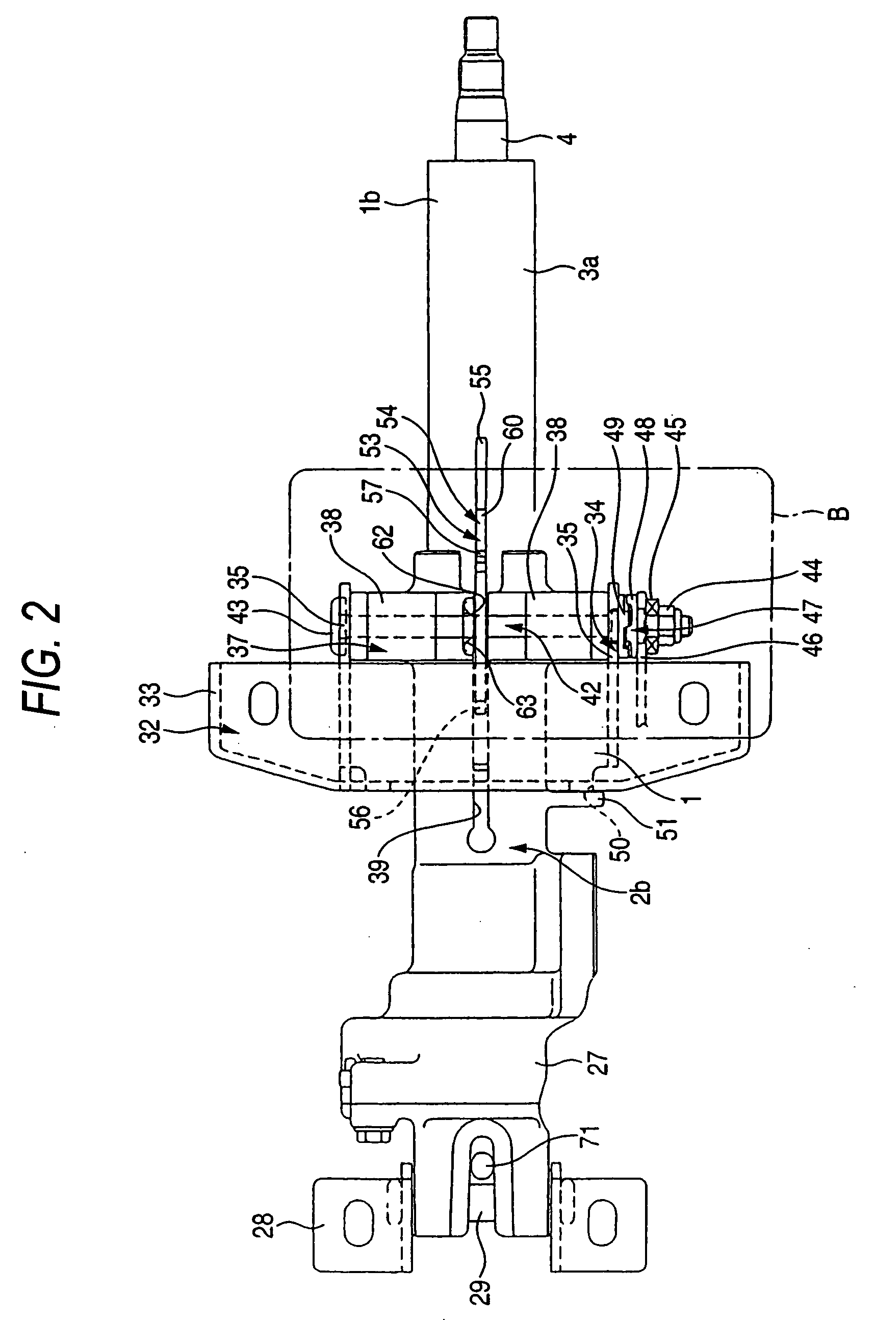
[0055] FIGS. 1 to 8 are views showing Embodiment 1 of the present invention. In a collapsible steering column device having a telescopic mechanism of this embodiment, a steering shaft 4, to the rear end portion of which a steering wheel 21 is fixed, is pivotally inserted into a steering column 1b. Entire lengths of the steering shaft 4 and the steering column 1b are contracted when they are given a load not less than a predetermined value in the front direction. In the steering column 1b, a cylindrical face portion provided in an outer circumferential face of a front end portion (the left end portion shown in FIGS. 1, 2, 4, 6, 7 and 8) of the inner column 3a is slidably, inwardly engaged with a partial cylindrical face portion provided on an inner circumferential face of a rear end portion (the right end portion shown in FIGS. 1, 2, 4, 6 and 8) of an outer column 2b via a plurality of spacers 26, 26 (three spacers in the case shown in the drawing). Each spacer 26, 26 is made of meta...

embodiment 2

[0072]FIG. 9 is a view showing Embodiment 2 of the present invention. In this embodiment, a forward end portion of the inner column 3a is directly, slidably inserted into a rear end portion of the outer column 2b without providing a spacer. Further, a coating layer 65 is directly provided on the inner circumferential face of the rear end portion of the outer column 2b without using a spacer. This coating layer 65 is the same as that provided on the inner circumferential face of the spacer 26 (shown in FIGS. 1, 3, 5, 6) used in Embodiment 1 described before. Further, in this embodiment, on the outer circumferential face of the forward end portion of the inner column 3a, the same coating layer 66 as that provided in the outer column 2b is directly provided. In this connection, in this embodiment in which the coating layer 66 is provided on the outer circumferential face of the inner column 3a, it is difficult to reduce an electric resistance of this coating layer 66 portion. Therefore...

embodiment 3

[0080] Next, FIGS. 10 to 12 are views showing Embodiment 3 of the present invention. In this embodiment, a bolt 42 is fixed to the outer column 2b in such a manner that the bolt 42 and the outer column 2b are contacted and electrically continued to each other. A spring member 67, which is an elastic body, is outwardly engaged with a columnar portion, which is provided in an intermediate portion of this bolt 42 and which is exposed between a pair of arm portions 38, 38. This spring member 67 is formed into a shape, the cross section of which is a substantial C-shape, out of conductive material such as metal, for example, spring steel. Through-holes 69, 69 are formed at positions in an intermediate portion of a pair of side wall portions 68, 68 configuring this spring member 67. A plurality of arcuate protruding pieces 70a, 70b are respectively formed in the outer end side opening circumferential edge portions of the through-holes 69, 69 in the side wall portions 68, 68. Forward end e...


PUM


Abstract

A stopper member 54 is fixed to an inner column 3a, and a second displacement preventing protruding portion 57 provided in the stopper member 54 is opposed to a bolt 42 fixed to an outer column 2b. In the case where a load not less than a predetermined value is given from the bolt 42 to the second displacement preventing protruding portion 57, the second displacement preventing protruding portion 57 is deformed and the thus deformed portion is withdrawn into an accommodating recess portion 60 provided in the stopper member 54. A plate spring made of conductive material is elastically pressed to the stopper member 54 and the outer column 2b in the circumferential direction of the outer column 2b.

Description

TECHNICAL FIELD [0001] The present invention relates to a collapsible steering column device having a telescopic mechanism, by the structure of which a shock given to a driver at the time of collision can be absorbed so as to protect life of the driver and further it is possible to adjust a position of a steering wheel in the longitudinal direction according to a physical constitution of the driver. RELATED ART [0002] At the time of automobile collision, after a so-called primary collision in which one automobile collides with another one, a so-called secondary collision occurs in which a driver collides with a steering wheel. For the object of reducing an intensity of the shock given to the driver at the time of the secondary collision and protecting life of the driver, it is common to configure a steering column device in such a manner that a steering shaft, at one end of which the steering wheel is fixed, is made into a so-called collapsible steering shaft, the entire length of w...

Claims


Application Information

Patent Timeline
Patent Type & Authority Applications(United States)
IPC IPC(8): B62D1/18B60R21/05B62D1/19
CPCB62D1/195
Inventor KAMEI, KOJI
Owner NSK LTD
Why Eureka
Try Eureka