Etching apparatus and etching method

a technology of etching apparatus and etching method, which is applied in the direction of electrical equipment, decorative arts, electric discharge tubes, etc., can solve the problems of increasing the cost of the fabricating process, lowering the process reliability, and either cannot effectively solve the above polymer issue, so as to prevent the non-uniform thickness of the polymer, the effect of high uniformity

Inactive Publication Date: 2007-06-21
UNITED MICROELECTRONICS CORP
View PDF15 Cites 12 Cited by
  • Summary
  • Abstract
  • Description
  • Claims
  • Application Information

AI Technical Summary

Benefits of technology

[0009] Accordingly, this invention provides an etching apparatus with higher uniformity in the temperature distribution of the etching chamber, so as to prevent a thickness non-uniformity of the polymer adhering to the interior surface of the etching chamber.
[0014] Because the portion of the plate body of the gas distribution plate corresponding to the outlet of the gas pipe has no through holes therein and the other portion of the plate body and the inner collar-shaped part each has multiple through holes therein, the introduced gas can be distributed more evenly than before. Thus, the central part of the exterior surface of the etching chamber does not tend to be colder than the other parts, so that the polymer adhering to the interior surface of the same is more uniform in the thickness and does not easily peel off to contaminate the wafer surface.

Problems solved by technology

As a result, the process reliability is lowered and the period of the prevention maintenance (PM) cycle is shortened, thus increasing the cost of the fabricating process.
However, the method either cannot effectively solve the above polymer issue.

Method used


Image

  • Etching apparatus and etching method
  • Etching apparatus and etching method
  • Etching apparatus and etching method

Examples


Embodiment Construction

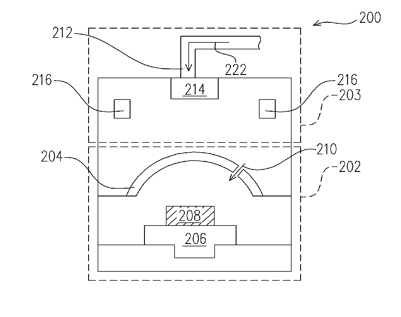
[0019] Referring to FIG. 3, the etching apparatus 200 includes an etching chamber 202 and a temperature control system 203. The etching chamber 202 usually includes a chuck 206 and a dome 204 disposed over the chuck 206, wherein the material of the dome 204 may be ceramic. The chuck 206 is for carrying and fixing a wafer 208 to be etched, and may be one capable of moving up and down such that the wafer 208 can be raised or lowered as required. The etching gas composition for generating the etching plasma may be introduced into the etching chamber 202 through a gas inlet 210 on the dome 204, and the electrodes for providing RF power to generate the etching plasma may be disposed in the etching chamber 202.

[0020] The temperature control system 203 includes a gas pipe 212, a gas distribution plate 214 and a heater 216 at least. The gas pipe 212 is disposed over the dome 204 for delivering a gas to the exterior surface of the latter, wherein the gas serves as a cooling source in the te...


PUM

PropertyMeasurementUnit
diameteraaaaaaaaaa
diameteraaaaaaaaaa
diameteraaaaaaaaaa

Abstract

An etching apparatus is described, including an etching chamber, a gas pipe, a gas distribution plate and a heater. The gas pipe is disposed above the etching chamber for delivering a gas to the exterior surface of the etching chamber. The gas distribution plate is disposed at the outlet of the gas pipe, including a plate body and an inner collar-shaped part thereon facing the outlet of the gas pipe. The inner collar-shaped part and the portion of the plate body around the inner collar-shaped part each has multiple through holes therein. The heater is disposed around the space between the gas pipe and the etching chamber for heating the gas flowing out of the gas distribution plate.

Description

BACKGROUND OF THE INVENTION [0001] 1. Field of the Invention [0002] The present invention relates to an etching equipment and an etching method. More particularly, the present invention relates to an etching apparatus with a higher uniformity in the temperature distribution of the etching chamber, and to an etching method using the same etching apparatus. [0003] 2. Description of the Related Art [0004] In an IC-fabricating process, a metal pattern is often defined by etching a metal layer with a lithographically patterned photoresist layer thereon as a mask to transfer the photoresist pattern to the metal layer. Hence, the metal etching process plays a very important role in IC fabrication. [0005] A metal etching process is usually conducted in a plasma etching apparatus, and a conventional plasma etching apparatus is depicted in FIG. 1. The etching apparatus 100 includes an etching chamber 103 that includes a chuck 104 for carrying and fixing a wafer 106 to be etched and a dome 102...

Claims


Application Information

Patent Timeline
Patent Type & Authority Applications(United States)
IPC IPC(8): C03C25/68H01L21/302H01L21/461H01L21/306
CPCH01J37/3244H01L21/31116H01L21/32136H01L21/32137H01L21/67069
Inventor HSIEH, CHUAN-HANLIU, YU-MINGLI, CHIU-LIANGHSU, HUI-CHINYEH, KUO-CHIHCHENG, HUNG-TEHSU, CHIEN-EN
Owner UNITED MICROELECTRONICS CORP
Why Eureka
Try Eureka