Integrated current sensor

a current sensor and integrated technology, applied in the field of current sensors, can solve the problems of low loss, circuit to have a higher cost, high loss provided by circuit,

Inactive Publication Date: 2007-06-21
POINT SIX WIRELESS +1
View PDF26 Cites 21 Cited by
  • Summary
  • Abstract
  • Description
  • Claims
  • Application Information

AI Technical Summary

Problems solved by technology

The problem with this approach is the high loss provided by the circuit.
While this approach has a low loss, the use of the hall effect device 202 causes the circuit to have a higher cost, and the accuracy and noise issues are greater within the hall device as the hall voltage is a small value.
This circuit requires the use of special technology which raises the cost of the device.
Additionally, accuracy issues arise even though the current may be sensed with very low loss.
While current transformers work well for detecting currents, they are large and have a medium loss level associated therewith.
The voltage induced in a Rogowski coil is very small and easily disturbed when measured current is less than, for example, 100 Amps.

Method used


Image

  • Integrated current sensor
  • Integrated current sensor
  • Integrated current sensor

Examples


Embodiment Construction

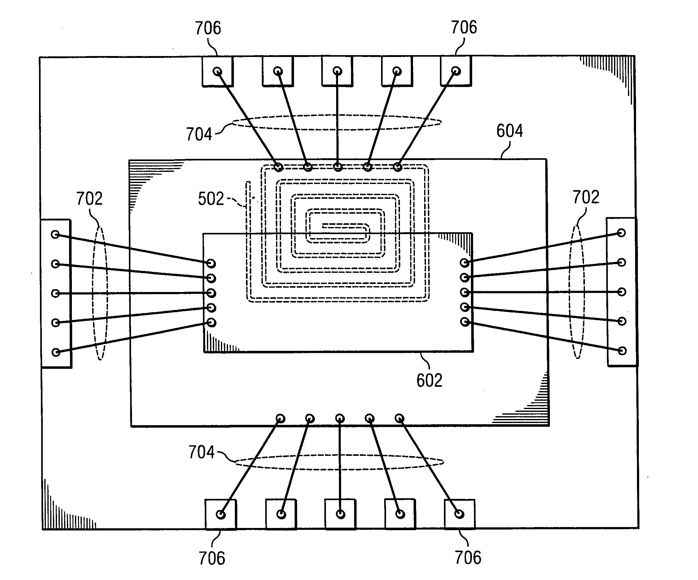
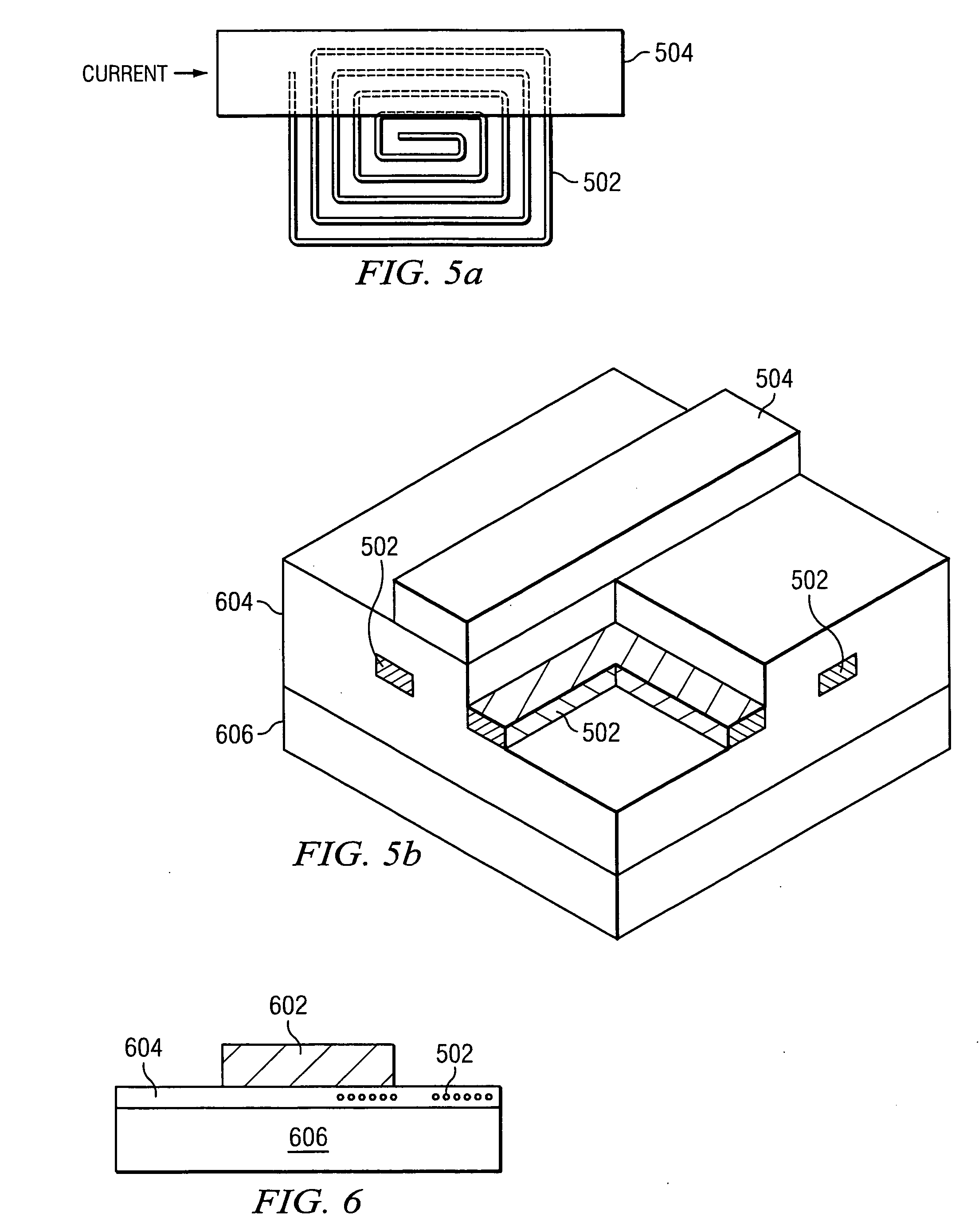
[0028] Referring now to the drawings, and more particularly to FIG. 5a, there is illustrated a coil 502 in close proximity with a large current carrying wire 504 such that the coil 502 and current carrying wire 504 act as coupled inductors. The coupled inductors, along with on-chip electronics which will be discussed herein below, allow the creation of the VSENSE signal which is proportional to the input current Ip in a manner that has very low loss, is very small and is a low cost implementation. This provides a better solution than all of the implementations described with respect to FIGS. 1-4. The current provided through the current carrying wire may be up to 10 amps. The coil 502 is placed very near the current carrying wire 504 in order to create the inductive coupling between the wire 504 and coil 502. The wire 504 only overlaps only one side of the coil 502 such that the winding are all going the same way and the magnetic flux will add together. This causes an induced curren...


PUM


Abstract

A current sensor includes coupled inductors that generate an output current responsive to a detected current. The coupled inductor is implemented in an integrated circuited. An integrator circuit generates a sensed voltage responsive to the output current.

Description

TECHNICAL FIELD OF THE INVENTION [0001] The present invention relates to current sensors, and more particularly, to an improved current sensor having low loss, small size, low cost and high accuracy. BACKGROUND OF THE INVENTION [0002] Within various circuit implementations, such as power supplies, there is often the need to detect a current provided at a particular point within a circuit to use as feedback for controlling other parts of the circuit. Various solutions are presently used to sense currents within electronic circuits but each of these suffer from various shortcomings. A first approach, illustrated in FIG. 1, utilizes a resistor 102 connected across the inputs of an operational amplifier 104 to provide a voltage VSENSE that may be used to determine a current 106. A low value resistor 102 may be used in the range of 10 milliohms. The problem with this approach is the high loss provided by the circuit. This may be overcome by reducing the resistor 102 to reduce the loss, h...

Claims


Application Information

Patent Timeline
Patent Type & Authority Applications(United States)
IPC IPC(8): G01R5/14G01R13/00
CPCG01R15/181H01L2224/48091H01L2224/4826H01L2224/49111H01L2224/49171H01L2224/45147H01L2924/00014
Inventor DUPUIS, TIMOTHY J.PAVELKA, JOHN
Owner POINT SIX WIRELESS
Why Eureka
Try Eureka