Antenna and method of manufacturing the same, and portable wireless terminal using the same

a portable wireless terminal and antenna technology, applied in the direction of waveguide type devices, elongated active element feeds, resonance antennas, etc., can solve the problems of not revealing a multi-mode antenna of three or more modes, difficult to suppress the overall dimension or volume of the multi-mode antenna small, etc., to reduce interference and expand the frequency bandwidth

Inactive Publication Date: 2007-06-21
HITACHI CABLE
View PDF7 Cites 62 Cited by
  • Summary
  • Abstract
  • Description
  • Claims
  • Application Information

AI Technical Summary

Benefits of technology

[0045] As described in the foregoing, according to the present invention, it is possible to realize an antenna that operates in multiple modes including three or more modes. That is, using a narrow band conductor, a linear conductor, or a narrow strip conductor that can be used as a transmission line, it is possible to design a multi-mode antenna having three modes or more due to the distributed constant circuit theory. Further, the problem of reducing the interference between radiation conductors, which arises in the integration of plural antenna structures as in the prior art, is obviated, which significantly contributes to realizing a compact multi-mode antenna and expanding the frequency bandwidth that is one of important characteristics of the antenna.

Problems solved by technology

Accordingly, as the frequencies of the electromagnetic waves to be radiated increase, the number of such independent structures increase, which makes it extremely difficult to suppress the overall dimension or volume of the multi-mode antenna small.
Indeed, Documents 1, 2 do not disclose a multi-mode antenna of three or more modes.

Method used


Image

  • Antenna and method of manufacturing the same, and portable wireless terminal using the same
  • Antenna and method of manufacturing the same, and portable wireless terminal using the same
  • Antenna and method of manufacturing the same, and portable wireless terminal using the same

Examples


first embodiment

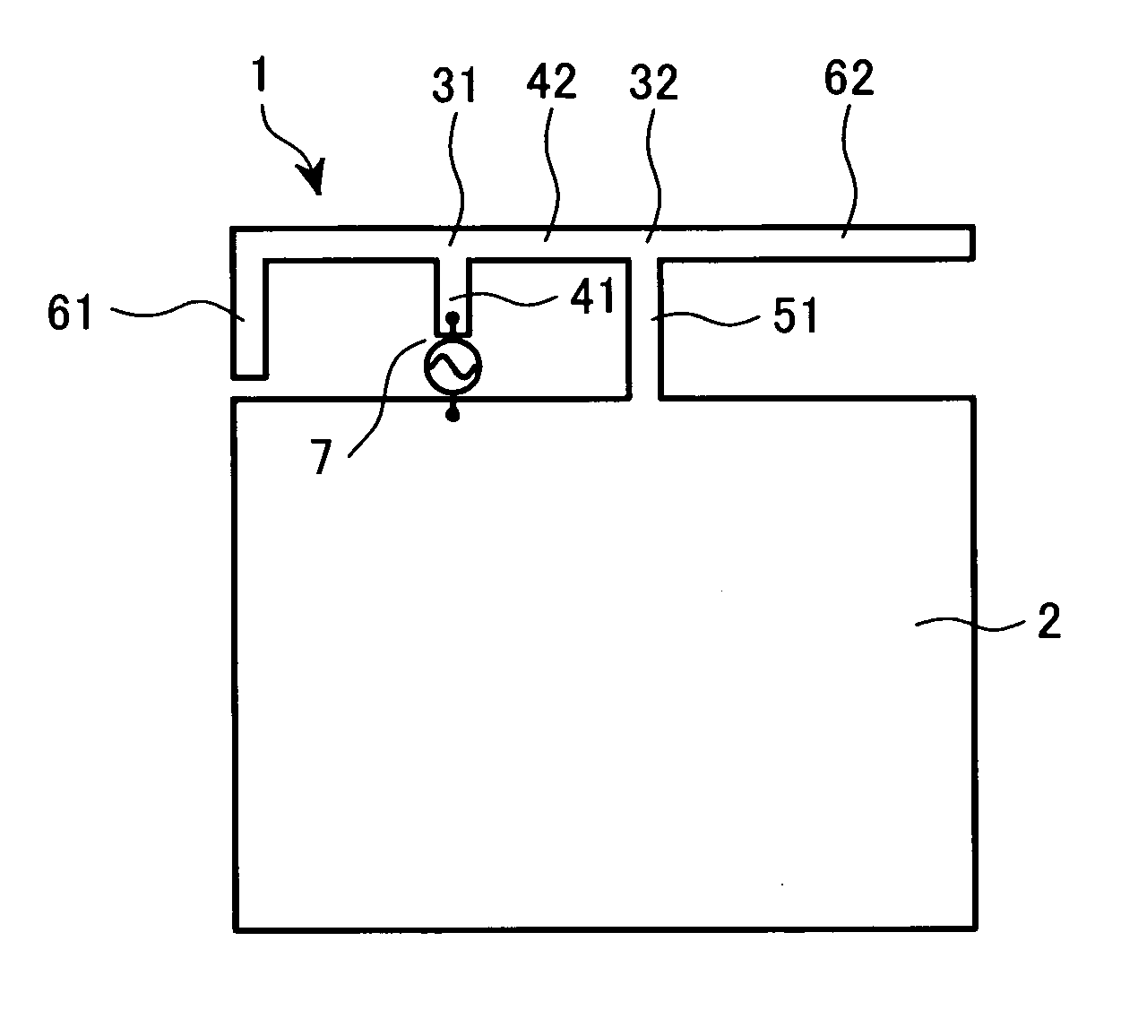
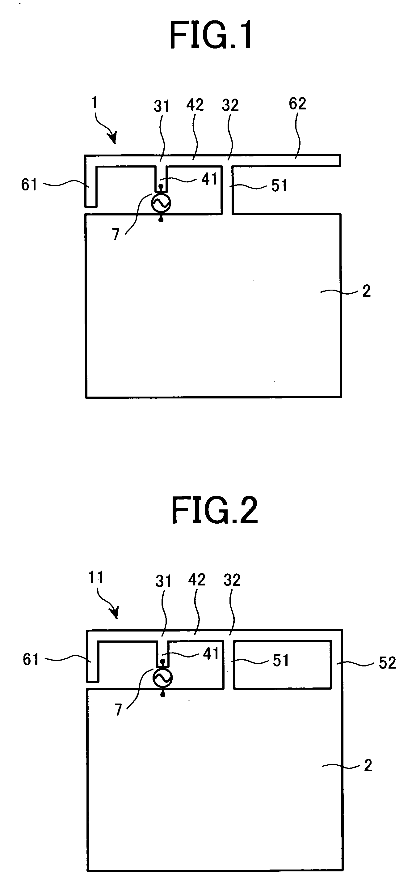
[0075]FIG. 1 shows the present invention. This embodiment provides a three-mode antenna. An antenna 1 is composed of a ground conductor (grounding portion) 2, branching points 31, 32, and transmission lines 41, 42, 51, 61, and 62 which are integrated together. A feeding point 7 for supplying electric power is formed between one end of the transmission line 41 and a part of the ground conductor 2. Further, the antenna 1 according to this embodiment consists of an integrated metal plate.

[0076] The first branching point 31, which is bifurcated, is connected to the first transmission line 41 that is extended from the feeding point 7 vertically with respect to the ground conductor 2. The first open stub 61 is connected to one end of the first branching point 31, and the second transmission line 42 is connected to the other end of the first branching point 31 while being arranged in parallel to the ground conductor 2. Further, the second branching point 32 that is bifurcated is connected ...

third embodiment

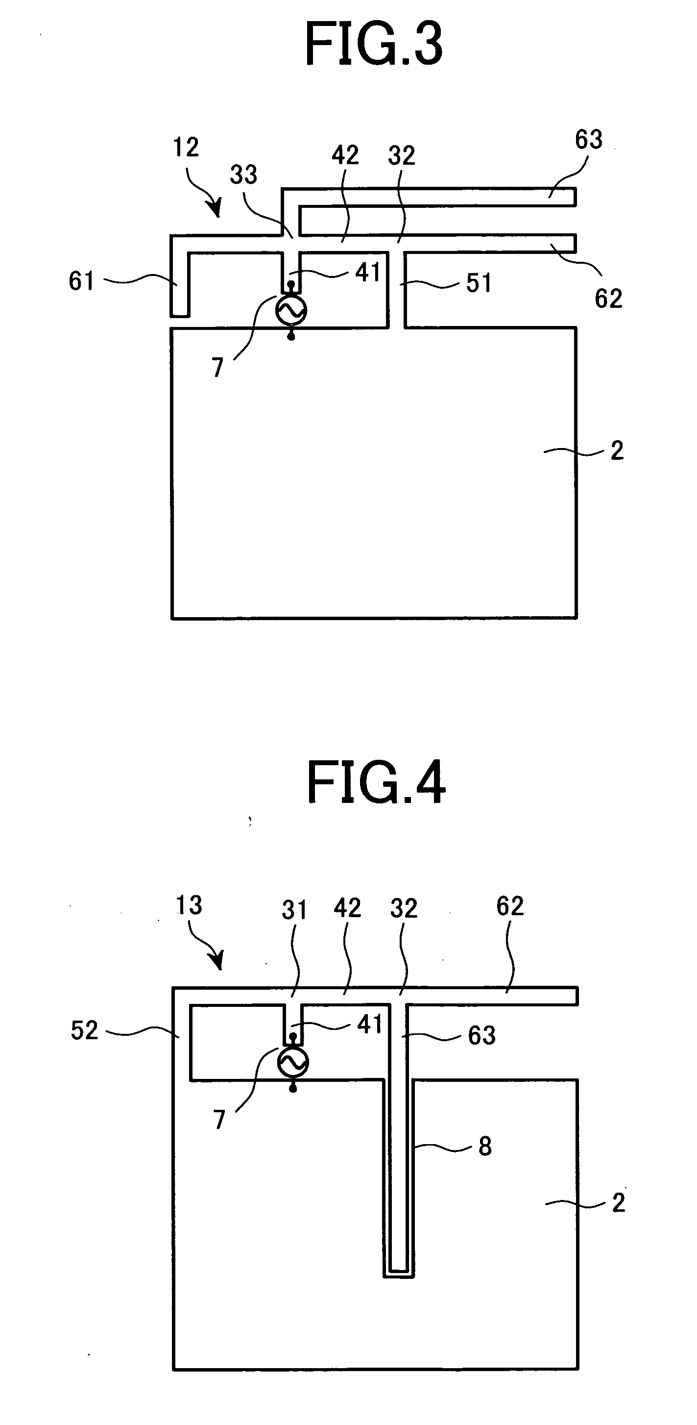
[0083]FIG. 3 shows the present invention. An antenna 12 shown in FIG. 3 is a three-mode antenna of a structure in which the branching point 31 that is bifurcated in the antenna 1 shown in FIG. 1 is replaced by a branching point 33 that is trifurcated, with another open stub 63 being connected to the branching point 33, thereby increasing the number of elements constituting the antenna.

[0084] The structure for increasing the number of elements allows the number of parameters of the distributed constant circuit network to be increased, whereby in addition to the effect of the antenna 1 shown in FIG. 1, it becomes possible to perform fine adjustment on the real part of the antenna input impedance at the feeding point.

[0085] In this embodiment, as an example of a set of three frequencies, the shortest wavelength λ1=104.7 mm, the middle wavelength λ2=219.8 mm, and the longest wavelength λ3=322.6 mm are selected. Further, the lengths of the transmission lines are set as follows: the tran...

fourth embodiment

[0086]FIG. 4 shows the present invention. An antenna 13 shown in FIG. 4 is a three-mode antenna of a structure in which a groove 8 is formed in a part of-the ground conductor 2, with the open stub 63 being received within the groove 8.

[0087] In FIG. 4, the branching point 31 that is bifurcated is connected to the first transmission line 41 extended from the feeding point 7 vertically with respect to the ground conductor 2. The short stub 52 is formed between one end of the first branching point 31 and the ground conductor 2. The second transmission line 42 is connected to the other end of the first branching point 31 so as to be parallel to the ground conductor 2. Further, the second branching point 32 that is bifurcated is connected ahead of the second transmission line 42 extending from the first branching point 31. The first open stub 62 is connected to one end of the second branching point 32 so as to be parallel to the ground conductor 2. The second open stub 63, which is exten...


PUM


Abstract

A small antenna operating in multiple modes including three or more modes. There are provided an antenna that includes a ground conductor having a ground potential, a single feeding point whose one end is formed by a part of the ground conductor, and a plurality of transmission lines to which RF power supplied to the feeding point is input, the transmission lines each radiating electromagnetic waves of three frequencies of three modes into space. These transmission lines comprises a transmission line 41 that is connected to the feeding point at one end and to a branching point at the other end, a transmission line connected between branching points, and transmission lines connected to the branching points. The lengths of the respective transmission lines are set so that impedance matching is performed at the feeding point with respect to a plurality of frequencies. The antenna is formed from an integrated metal plate.

Description

FIELD OF THE INVENTION [0001] The present invention relates to an antenna of a wireless terminal for providing multimedia services to the user. More specifically, the present invention relates to a multi-mode antenna suitable for use in a multimedia wireless terminal for performing plural services through information transmission using electromagnetic waves of different frequencies as the medium, a method of manufacturing the antenna, and a portable wireless terminal using the antenna. BACKGROUND OF THE INVENTION [0002] Recent years have seen increasing use of multimedia services in which various services relating to information transmission or information provision are provided by use of radio. Numerous wireless terminals have been developed to this end and put into practical use. The applications of these services have become increasingly diversified to include telephones, televisions, LANs (Local Area Networks), and so on. To enjoy all of these services, the user is required to o...

Claims


Application Information

Patent Timeline
Patent Type & Authority Applications(United States)
IPC IPC(8): H01Q1/38H01P11/00H01Q1/24H01Q5/00H01Q5/10H01Q5/357H01Q5/371H01Q9/42H01Q13/08H04M1/02
CPCH01Q1/243H01Q5/357H01Q9/42H01Q1/38H01Q1/24H01Q5/00H01Q9/04
Inventor TAKEI, KENOGAWA, TOMOYUKIIKEGAYA, MORIHIKOFUKUCHI, KEISUKE
Owner HITACHI CABLE
Why Eureka
Try Eureka