Control system and method for differentiating multiple users utilizing multi-view display devices

a display device and control system technology, applied in the field of user controls, can solve the problems of one user operating the physical user interface of the system, unable to easily distinguish which particular user, and inability to record the history of which users operated which controls,

Inactive Publication Date: 2007-06-21
MITSUBISHI ELECTRIC RES LAB INC
View PDF8 Cites 63 Cited by
  • Summary
  • Abstract
  • Description
  • Claims
  • Application Information

AI Technical Summary

Problems solved by technology

Conventional systems have no way for easily distinguishing which particular user has activated a particular control.
In addition, there is no way to record a history of which users operated which controls.
However, in this case, it is presumed that only one user operates the physical user interface of the system, e.g., a workstation, after logging on.
The system has no way of knowing whether multiple users are interacting with the interface.
Unfortunately, that system is not designed for user interface applications, such as control panels.
Adding PAN-type interfaces to many controls is prohibitively expensive.
Also, there are significant data collision problems to solve when multiple controls are operated concurrently by a single user.
However, that system requires a fingerprint sensor in every device and is not suitable for small controls, such as switches, and user interface applications including a large number of controls.
In addition, the cost of integrating a fingerprint sensor into every control is prohibitive.
However, the DiamondTouch system is restricted to specialized touch surfaces with a pattern of embedded antennas.

Method used


Image

  • Control system and method for differentiating multiple users utilizing multi-view display devices
  • Control system and method for differentiating multiple users utilizing multi-view display devices
  • Control system and method for differentiating multiple users utilizing multi-view display devices

Examples


Embodiment Construction

System Overview

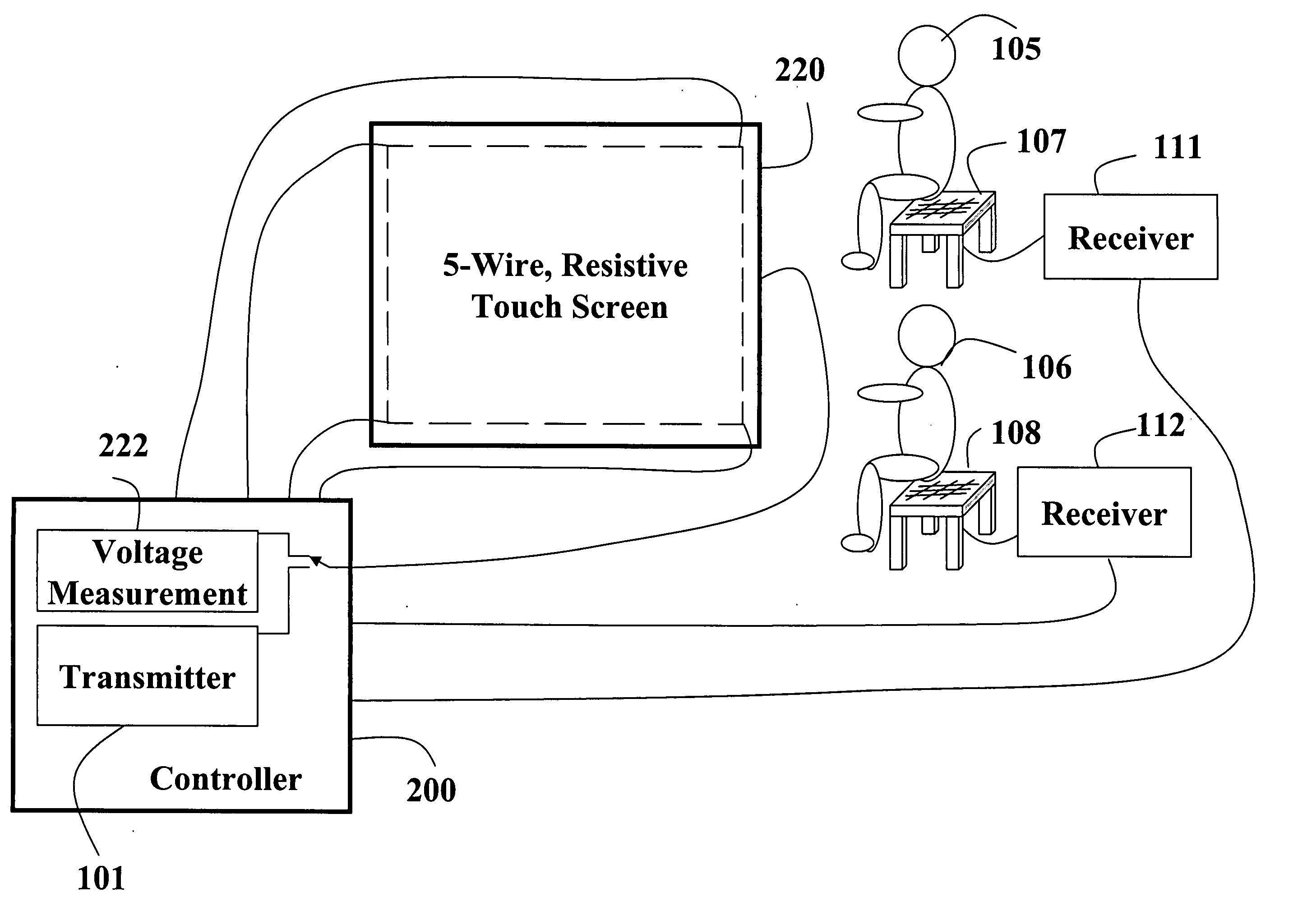
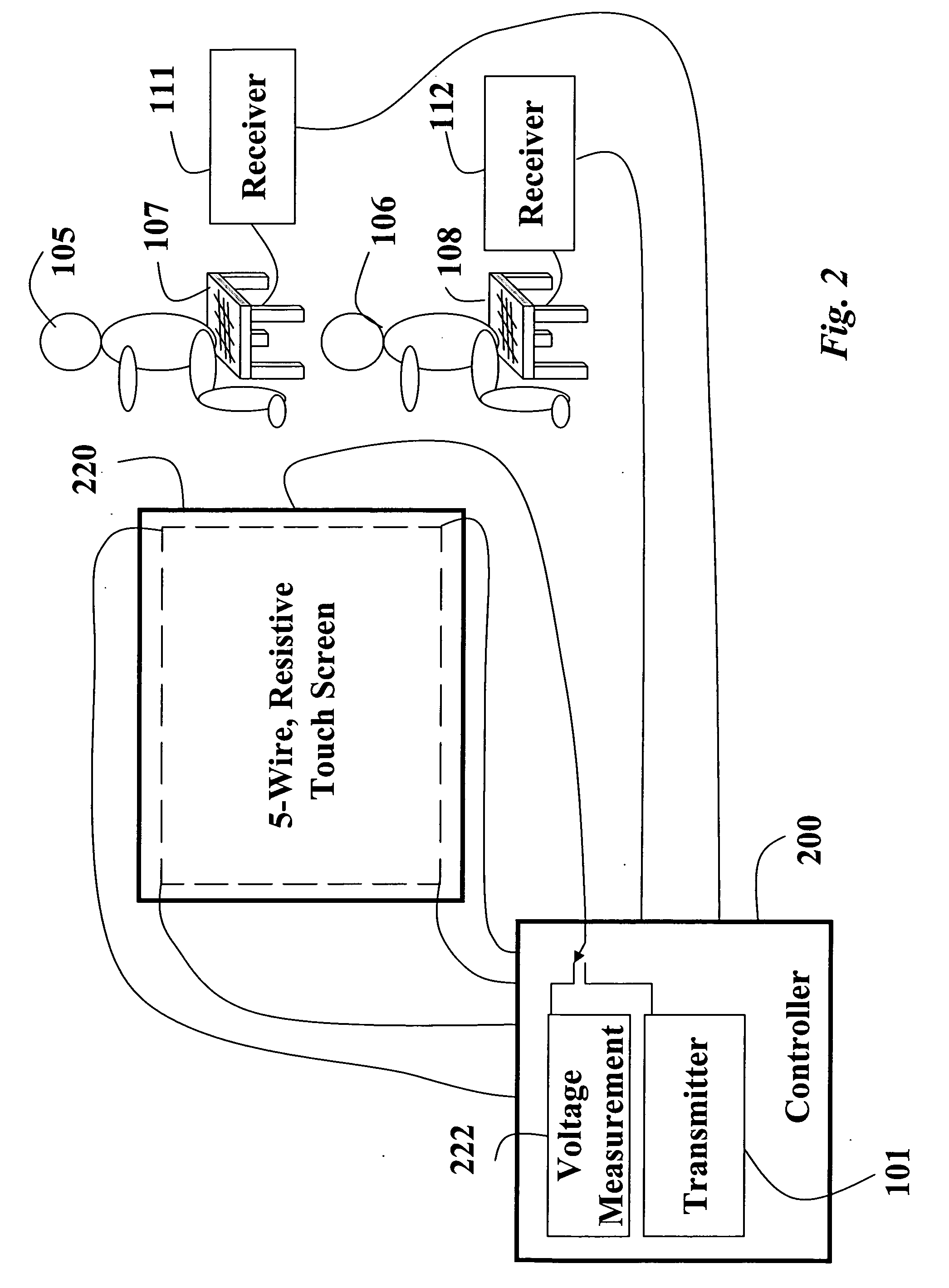
[0021] The invention differentiates operations and behaviors of controls of systems according to different users. The invention is concerned with systems that are typically included in control rooms, airplanes, and vehicles, to name but a few examples. It is desired to operate the system dependent upon the particular users actuating the controls. Both the system functionality and behavior may vary according to the different users. Behavior refers to the ‘look and feel’ of a control. For example, the behavior can be altered by haptic feedback.

Controls

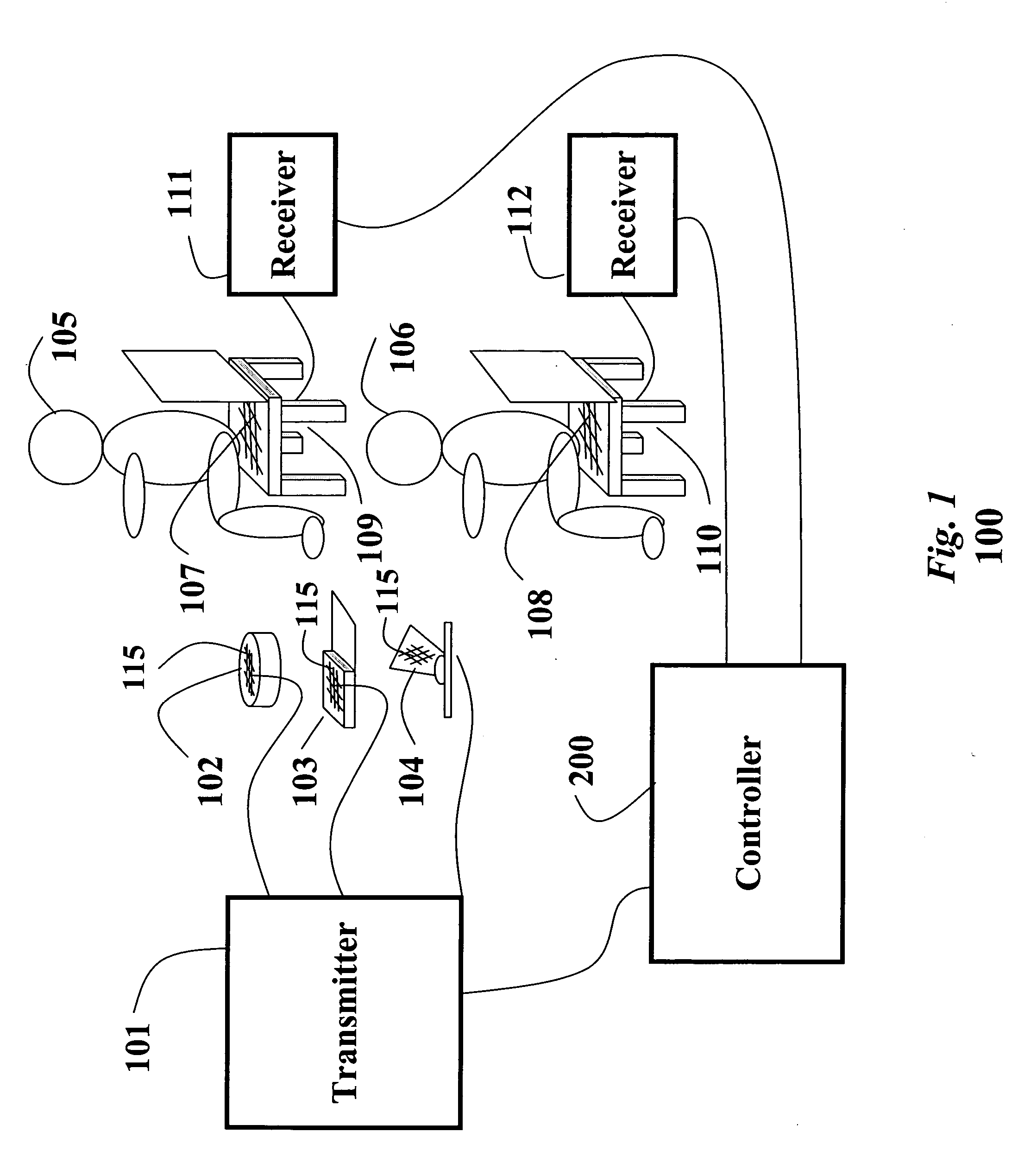
[0022] In the preferred embodiment of the invention, controls of the system are associated with corresponding conductive surfaces. Each conductive surface is connected to a transmitter that emits a uniquely identifiable signal associated with the control. The conductive surfaces are arranged so that a user is in a close physical proximity to the conductive surface in order to operate the corresponding control.

[0023] ...


PUM


Abstract

A system differentiates user controls by arranging a conductive surface in a close approximation to each control. A transmitter is connected to the conductive surfaces. The transmitter emits a unique signal to each conductive surface. Electrodes are arranged in close proximity to users of the controls, and a receiver is connected to each corresponding electrode. A particular user is associated with a particular control when the particular user is capacitively coupled to a particular conductive surface via the electrode, the receiver and the transmitter. Images are displayed to the users using display devices. The display devices present concurrently multiple images to multiple users. The controls may include virtual controls displayed as icons on a touch-sensitive surface displaying the images.

Description

CROSS-REFERENCE TO RELATED APPLICATIONS [0001] This application is a continuation-in-part of U.S. patent application Ser. No. 11 / 098,089, “Control System for Differentiating Multiple Users,” filed by Dietz et al. on Apr. 4, 2005.FIELD OF THE INVENTION [0002] This invention relates generally to user controls, and more particularly to user controls that differentiate particular users touching the controls. BACKGROUND OF THE INVENTION [0003] Plant control rooms, airplane cockpits and vehicle dashboards typically include a large number of physical user controls, e.g., control switches, keyboards, mice, touch screens, etc., that can be used concurrently by multiple users to operate systems. Conventional systems have no way for easily distinguishing which particular user has activated a particular control. Thus, all controls operate identically for every user. In addition, there is no way to record a history of which users operated which controls. [0004] There are single user systems that...

Claims


Application Information

Patent Timeline
Patent Type & Authority Applications(United States)
IPC IPC(8): G09G5/00G06F12/14G08B13/00
CPCG06F3/011G06F3/038
Inventor HARSHAM, BRET A.AIKAWA, MASAMIMATSUBARA, TSUTOMUMIYAZAKI, HIDETO
Owner MITSUBISHI ELECTRIC RES LAB INC
Why Eureka
Try Eureka