Display module for an electronic device

a display module and electronic device technology, applied in the field of display modules, can solve the problems of large distance between the pcb and the outer surface of the protective plate, affecting the effect of absorbing more effectively, increasing the robustness of the display module, and reducing the thickness of the electronic device in which the display is used

Inactive Publication Date: 2007-06-21
SONY ERICSSON MOBILE COMM AB
View PDF18 Cites 5 Cited by
  • Summary
  • Abstract
  • Description
  • Claims
  • Application Information

AI Technical Summary

Benefits of technology

[0008] A second aspect of the current invention is to provide a display module which allows the mechanical construction of the electronic device to be slimmer.
[0009] One or more of the above mentioned aspects may be addressed in part by a display module including at least two thin layers of rigid transparent material, such as glass or another similar material, with the display element and the at least two thin layers of rigid transparent material being part of a laminated structure where the different layers are attached together, for example with an adhesive. Since the display el

Problems solved by technology

However, this type of prior art assembly may suffer from the disadvantage that due to the air gap and the thick protective plate, the distance between the PCB and the outer surface of the protective plate may be quite large.
This means that the electronic device may become rather t

Method used


Image

  • Display module for an electronic device
  • Display module for an electronic device
  • Display module for an electronic device

Examples


Embodiment Construction

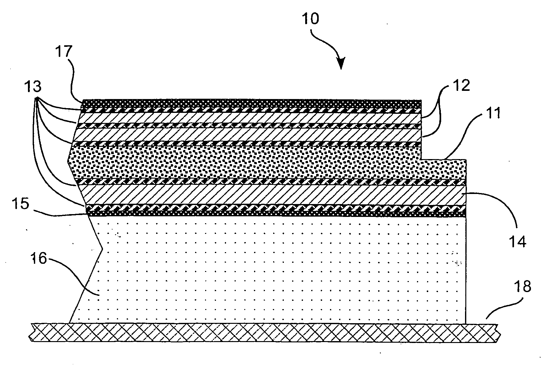
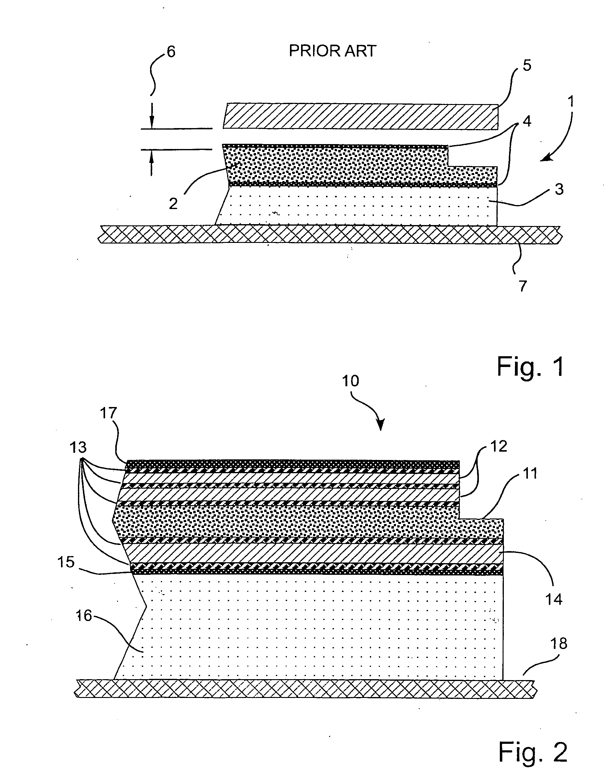
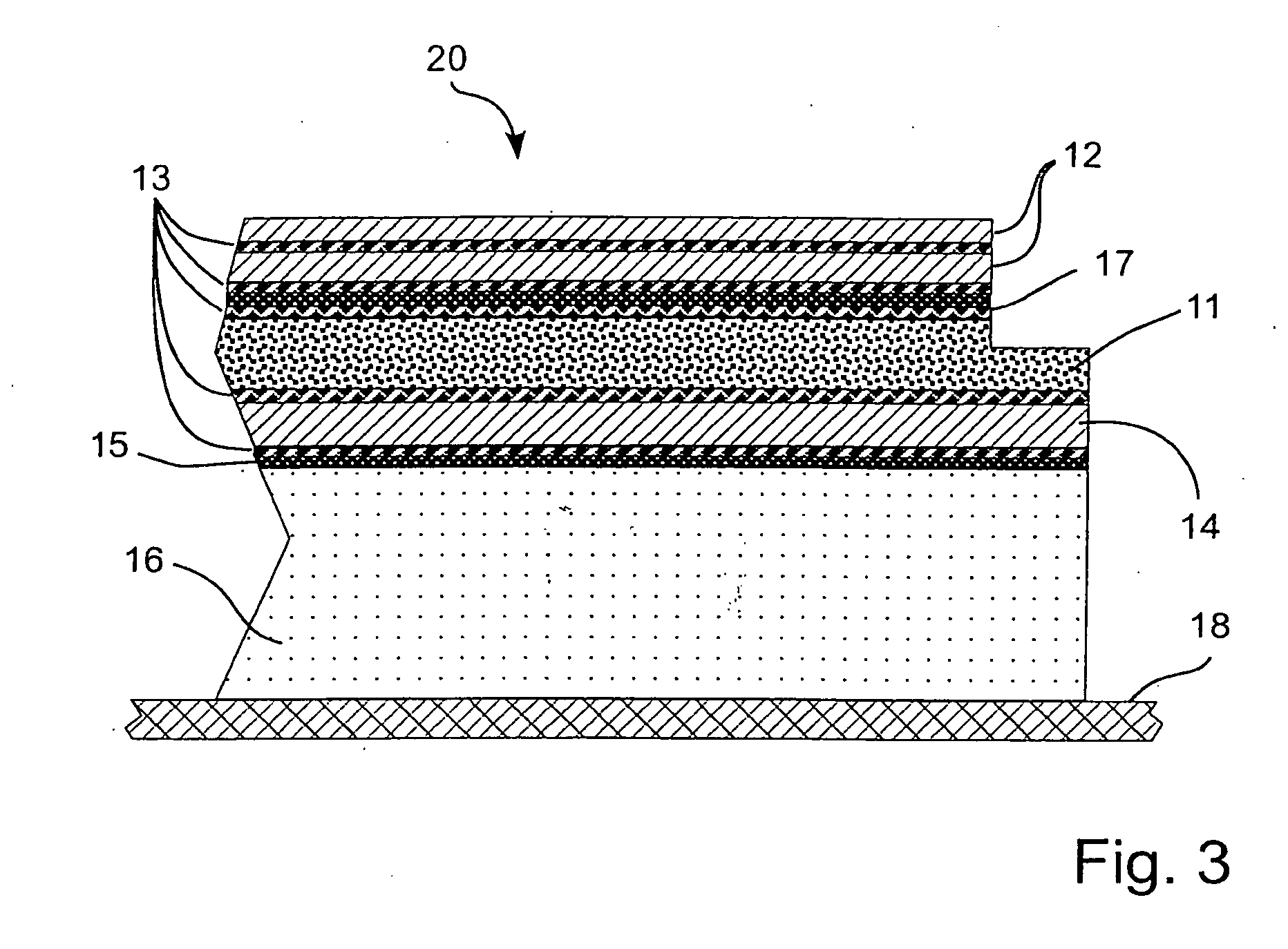
[0021] Embodiments of the present invention now will be described more fully hereinafter with reference to the accompanying drawings, in which embodiments of the invention are shown. This invention may, however, be embodied in many different forms and should not be construed as limited to the embodiments set forth herein. Rather, these embodiments are provided so that this disclosure will be thorough and complete, and will fully convey the scope of the invention to those skilled in the art. Like numbers refer to like elements throughout.

[0022] It will be understood that, although the terms first, second, etc. may be used herein to describe various elements, these elements should not be limited by these terms. These terms are only used to distinguish one element from another. For example, a first element could be termed a second element, and, similarly, a second element could be termed a first element, without departing from the scope of the present invention. As used herein, the te...


PUM


Abstract

A display module which is to be mounted on a printed circuit board of an electronic device includes a display element. The display module further includes at least two thin layers of a transparent material, such as glass or other similar material. The display element and the at least two thin layers of rigid transparent material are part of a laminated structure where the different layers of the laminated structure are attached together with an adhesive. In this way a stronger and more robust display module is provided. This allows the thickness of the housing of the electronic device to be reduced since there is no need for a protective glass plate and an air gap in front of the display module.

Description

REFERENCE TO RELATED APPLICATION [0001] This application claims the benefit of, and priority to, provisional Application No. ______, filed Dec. 20, 2005, entitled “Display Module Which Is To Be Mounted On A PCB,” Attorney Docket 9561-5PR, the disclosure of which is hereby incorporated by reference herein as if set forth in its entirety.FIELD OF THE INVENTION [0002] The current invention relates to display modules. In particular, the present invention relates to display modules that are configured to be mounted on a printed circuit board of an electronic device. BACKGROUND [0003] Display modules, which include display elements, are typically used in mobile electronic devices, such as mobile telephones, PDAs, personal music devices and so on. It should be mentioned that the term “display element” may include any type of element which acts as a display. A typical example is a Liquid Crystal Display (LCD). An LCD includes a transparent electrode plate arranged on each side of a liquid c...

Claims


Application Information

Patent Timeline
IPC IPC(8): G02F1/1333
CPCG02F1/133308G02F2001/133311G02F2001/13332G02F2201/503G02F1/133311G02F1/13332G02F1/1333G02F1/1345
Inventor HUNT, ALEXANDERGRIP, MARTIN
Owner SONY ERICSSON MOBILE COMM AB
Why Eureka
Try Eureka