[0007] In one embodiment of the
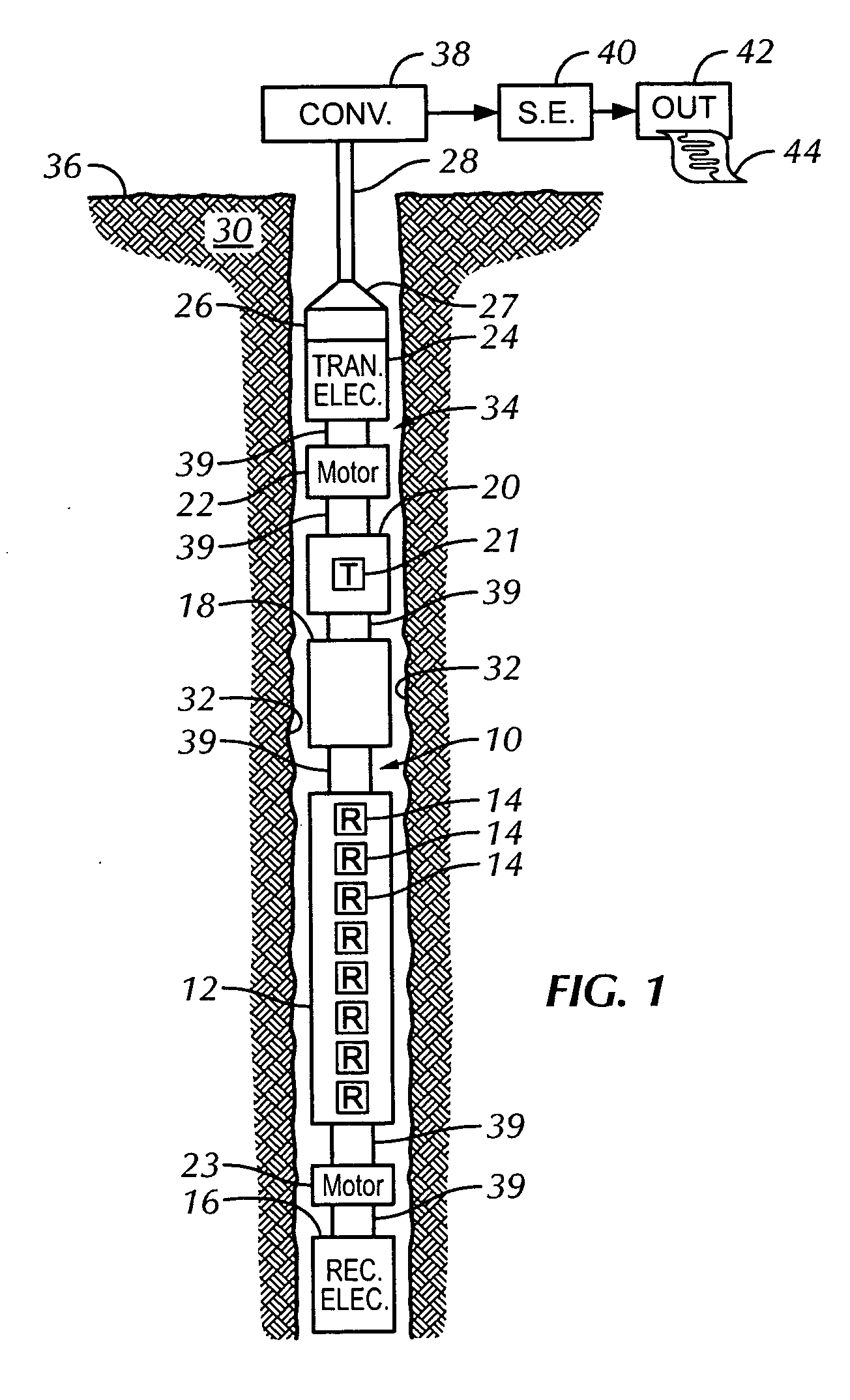
logging system, the transmitter assembly comprises a transmitter comprising a single
dipole transmitter element. The use of a single rotating transmitter element eliminates the need for balancing and calibration between transmitters. In addition, the use of a single rotating transmitter element eliminates the need to collocate signals from multiple, axially spaced transmitter elements to a common reference depth within the borehole. Prior art
collocation methods include, but are not limited to,
software collocation.
Elimination of the need to collocate transmitter signals improves accuracy in the determination of the
anisotropy formation properties since all
azimuth measurements in a given rotation are taken essentially at the same reference depth. The receiver assembly comprises at least two receivers axially spaced at different spacings from the transmitter assembly. Each receiver of the receiver assembly comprises a single receiver element that is radially aligned with the transmitter element. Both the transmitter and receiver assemblies are synchronously rotated about the axis of the tool thereby maintaining alignment between the transmitter element and the receiver elements.
Acoustic energy is transmitted as pulses into the formation as the transmitter assembly rotates. The single transmitter element transmits the same amount of
acoustic energy at every predetermined azimuthal position around the borehole. This eliminates the need to maintain calibration and balance of multiple transmitter elements, while logging, in the transmitter assembly.
Full wave acoustic data are recorded by each single, synchronously rotating receiver element comprising each receiver of the receiver array. For each receiver, the same receiver element measures
acoustic energy at every azimuthal orientation. This eliminates the need to maintain calibration and balance of multiple, azimuthally spaced receiver elements at a given axially spaced receiver. Shear wave velocities and amplitudes are determined from the response of each receiver element at each azimuthal orientation. These parameters are then combined and used to obtain borehole
anisotropy parameters of interest.
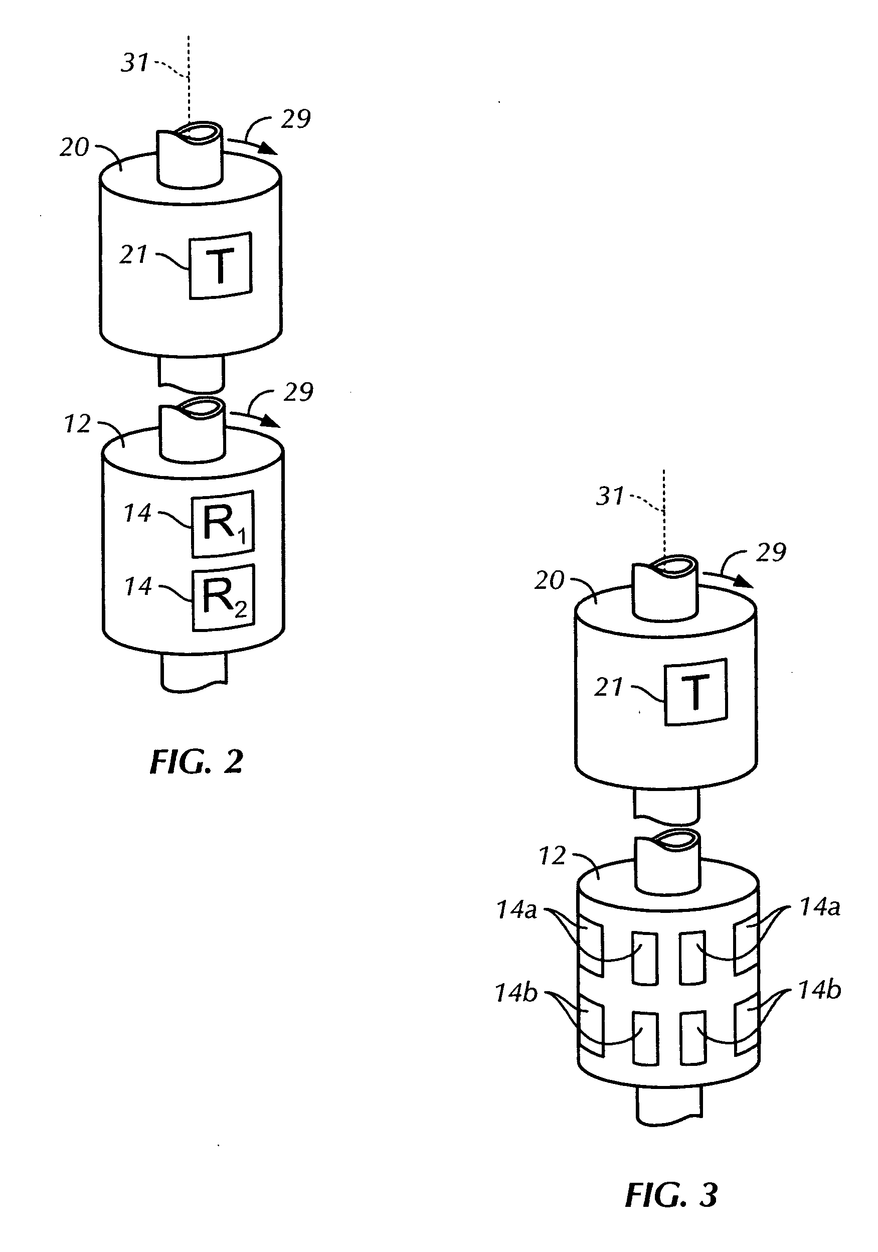
[0011] In yet another embodiment of the
logging system, the transmitter assembly comprises two
dipole transmitter elements disposed orthogonally in a plane perpendicular to the axis of the tool. The receiver assembly comprises an array of at least two receivers axially spaced at differing spacings from the transmitter assembly. Each receiver comprises a single receiver element. The transmitter assembly does not rotate about the axis of the logging tool.
Acoustic energy is transmitted as pulses at a 90 degree angle by the two orthogonal transmitter elements. Calibration and balance between the two transmitter elements must be obtained in order to obtain accurate and precise measures of the parameters of interest. The receiver assembly is rotated about the axis of the tool. Once again,
full wave acoustic data are recorded by each single rotating receiver element comprising each receiver of the receiver array. For each receiver, the same receiver element measures
acoustic energy at every azimuthal direction. This, as discussed previously, eliminates the need to maintain calibration and balance of multiple, azimuthally spaced receiver elements comprising a given axially spaced receiver. Again, shear
wave velocity and amplitude are determined, and borehole
anisotropy parameters are obtained by combining responses of the receiver elements.
[0012] In still another embodiment of the
logging system, the transmitter assembly comprises a single
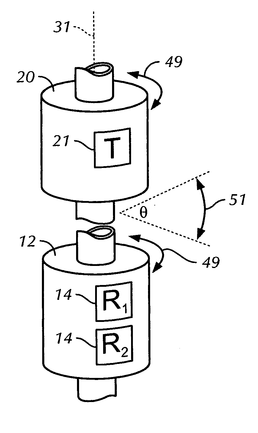
dipole transmitter element and the receiver array comprises at least two receivers axially spaced at differing spacings from the transmitter assembly. Each receiver comprises a single receiver element that is radially aligned with the transmitter element. Both the transmitter and receiver arrays are periodically and synchronously oscillated about the axis of the tool while maintaining alignment between the transmitter element and the at least two receiver elements. Oscillation, rather than rotation, eliminates certain electromechanical elements in the system, as will be discussed in a subsequent section of this disclosure.
Acoustic energy is again transmitted as pulses into the formation as the transmitter element oscillate. The single transmitter element transmits the same amount of acoustic energy at every location of an oscillatory arc. This, as in the rotating transmitter embodiments, eliminates the need to maintain calibration and balance between multiple transmitter elements.
Full wave acoustic data are recorded by each single, synchronously oscillating receiver element comprising each receiver of the receiver array. For each receiver, the same receiver element measures acoustic energy at every azimuthal
station, again eliminating the need to maintain relative receiver calibration and balance. Previously discussed shear wave related parameters of interest are determined by combining receiver element responses at predetermined azimuthal positions on the swept arc.

