
High performance equalizer with enhanced dfe having reduced complexity

a technology of dfe and complexity, applied in the field of communication system channel equalization improvement methods and apparatuses, can solve the problems of receiver sensitivity being affected by mlse use, and achieve the effect of reducing the complexity of an equalizer, reducing the effective delay spread of the channel, and reducing the complexity of the entire equalizer structur

Inactive Publication Date: 2007-06-21
AVAGO TECH INT SALES PTE LTD
View PDF18 Cites 52 Cited by
  • Summary
  • Abstract
  • Description
  • Claims
  • Application Information

AI Technical Summary

Benefits of technology

The proposed solution achieves reduced complexity and improved performance by effectively handling both minimum and maximum phase channels, making it suitable for high-order modulation schemes, while maintaining simplicity comparable to conventional DFEs.

Problems solved by technology

However, usage of the MLSE will come at the expense of receiver sensitivity.

Method used


Image

  • High performance equalizer with enhanced dfe having reduced complexity
  • High performance equalizer with enhanced dfe having reduced complexity
  • High performance equalizer with enhanced dfe having reduced complexity

Examples


Embodiment Construction

[0035] The present invention is described below in terms of certain preferred embodiments, and representative applications. The apparatus and processing methods are applicable to any wireless or wireline communication system where an equalizer is used to eliminate the ISI effects of the channel.

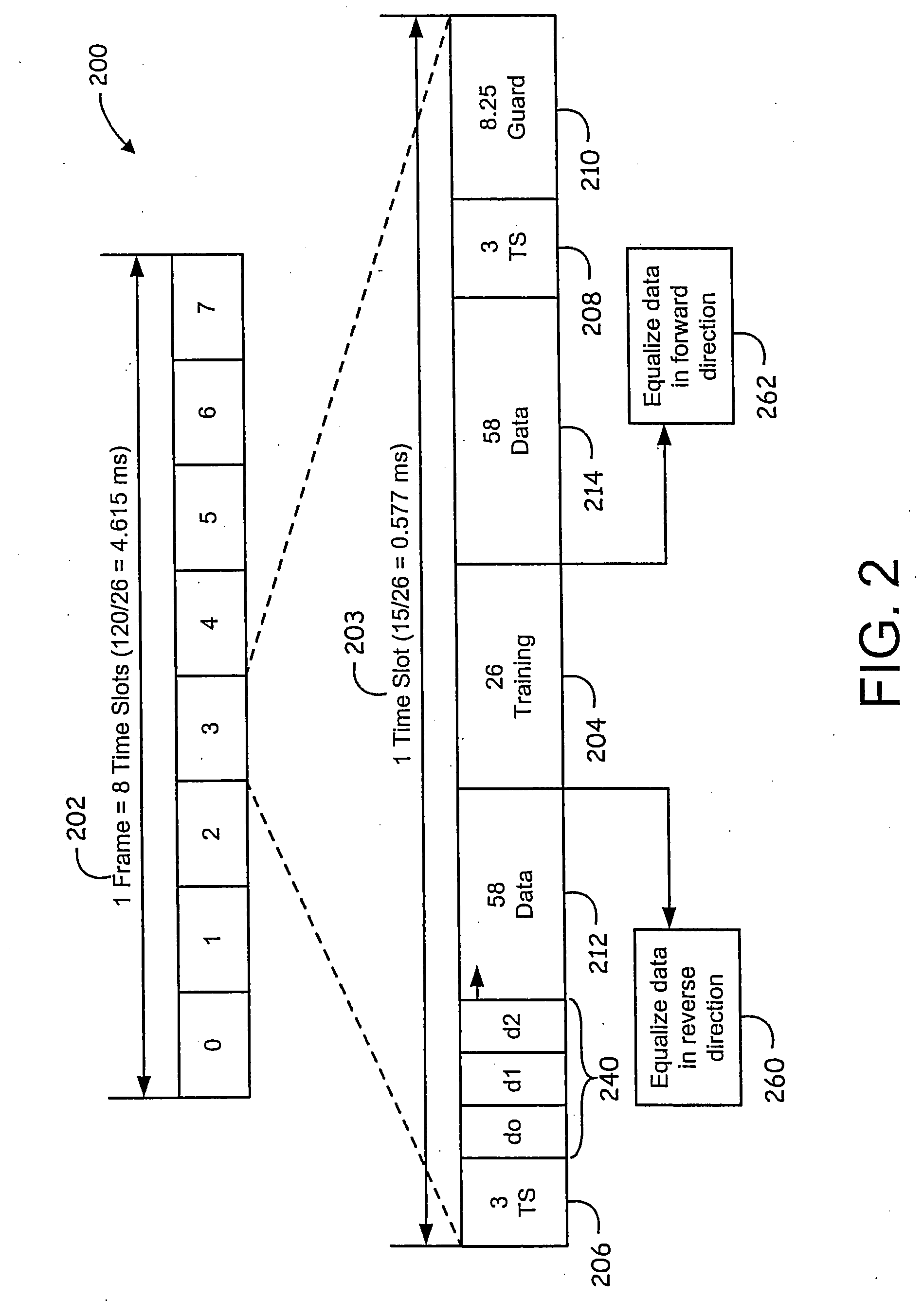
[0036] A representative application of the invention is the EDGE system, and a preferred embodiment is described below. Since radio spectrum is a limited resource, shared by all users, a method must be devised to divide up the bandwidth among as many users as possible. The GSM / EDGE system uses a combination of Time- and Frequency-Division Multiple Access (TDMA / FDMA). The FDMA part involves the division by the frequency of the (maximum) 25 MHz bandwidth into 124 carrier frequencies spaced 200 kHz apart. One or more carrier frequencies is assigned to each base station. Each of these carrier frequencies is then divided in time, using a TDMA scheme. The fundamental unit of time in this TDMA sche...


PUM


Abstract

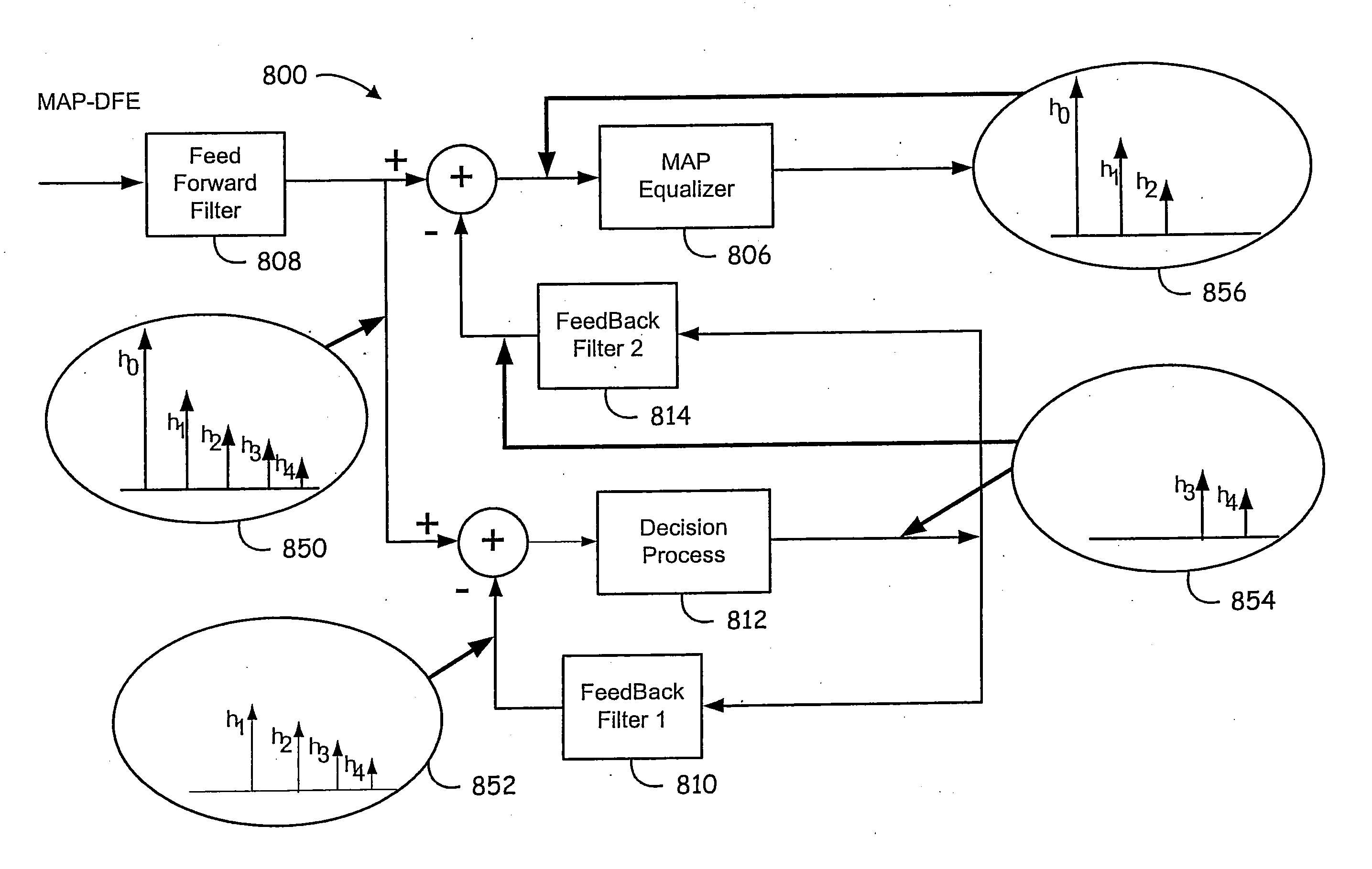
An apparatus and method for implementing an equalizer which (1) combines the benefits of a decision feedback equalizer (DFE) with a maximum-a-posterori (MAP) equalizer (or a maximum likelihood sequence estimator, MLSE) (2) performs equalization in a time-forward or time-reversed manner based on the channel being minimum-phase or maximum-phase to provide an equalization device with significantly lower complexity than a full-state MAP device, but which still provides improved performance over a conventional DFE. The equalizer architecture includes two DFE-like structures, followed by a MAP equalizer. The first DFE forms tentative symbol decisions. The second DFE is used thereafter to truncate the channel response to a desired memory of L1 symbols, which is less than the total delay spread of L symbols of the channel. The MAP equalizer operates over a channel with memory of L1 symbols (where L1<=L), and therefore the overall complexity of the equalizer is significantly reduced.

Description

RELATED APPLICATIONS [0001] This application is a continuation of U.S. patent application Ser. No. 09 / 946,648, filed Sep. 4, 2001, which claims priority of the following—U.S. Provisional patent application having Ser. No. 60 / 265,740 (Attorney Ref. No. 13153US01), entitled “A Decision Feedback Equalizer for Minimum and Maximum Phase Channels,” filed Feb. 1, 2001; U.S. Provisional patent application having Ser. No. 60 / 265,736 (Attorney Ref. No. 13152US01), entitled “Method For Channel Equalization For TDMA Cellular Communication Systems,” filed Feb. 1, 2001; and U.S. Provisional patent application having Ser. No. 60 / 279,907 (Attorney Ref. No. 13154US01), entitled “A Novel Approach to the Equalization of EDGE Signals,” filed Mar. 29, 2001; all of which are hereby incorporated by reference in their entirety. [0002] The application is also related to the following—U.S. patent application having Ser. No. 09 / 941,027 (Attorney Ref. No. 13153US02), entitled “Decision Feedback Equalizer for M...

Claims


Application Information

Patent Timeline
Patent Type & Authority Applications(United States)
IPC IPC(8): H03H7/30H04B1/10H03H7/40H04L25/03
CPCH04L25/03057H04L25/03076H04L25/03146H04L25/03171H04L25/03261H04L2025/03401H04L2025/0349H04L2025/0356H04L2025/03796
Inventor ALLPRESS, STEVE A.LI, QUINN
Owner AVAGO TECH INT SALES PTE LTD
Learn More