Moving-picture layered coding and decoding methods, apparatuses, and programs

Active Publication Date: 2007-06-21
COMCAST CABLE COMM LLC
View PDF3 Cites 31 Cited by
  • Summary
  • Abstract
  • Description
  • Claims
  • Application Information

AI Technical Summary

Benefits of technology

[0010] A purpose of the present invention is to provide layered coding and decoding methods, a

Problems solved by technology

The known layered video coding scheme, however, suffers elimination of high-frequency components, that are required In production of interlayer predictive signals, through base-layer spatial decimation.
The elimination may occur due to limited bandwidth in production of base-layer frames with a spatial scale down procedure.
The elimination of high-frequency components results in insufficient predictive coding to produce inaccurate enhancement-layer predictive frames based on correlation between

Method used


Image

  • Moving-picture layered coding and decoding methods, apparatuses, and programs
  • Moving-picture layered coding and decoding methods, apparatuses, and programs
  • Moving-picture layered coding and decoding methods, apparatuses, and programs

Examples


Embodiment Construction

[0027] Several preferred embodiments according to the present invention will be described in detail with reference to the drawings.

[0028] The same reference signs and numerals are used for the same or analogous components through the drawings in the following disclosure.

[0029] Described first with reference to FIGS. 1 to 3 are layered coding and decoding apparatuses according to the present invention.

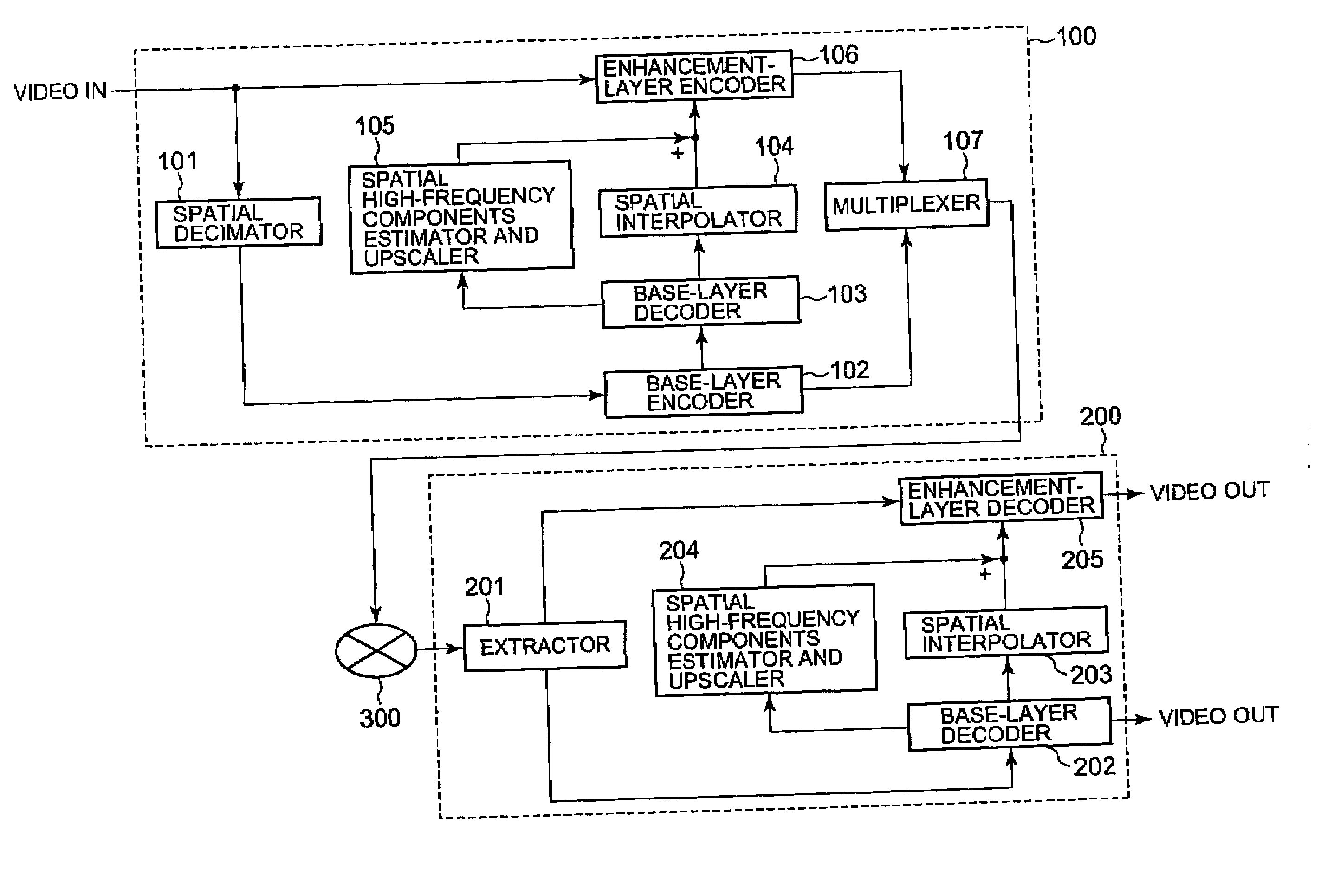
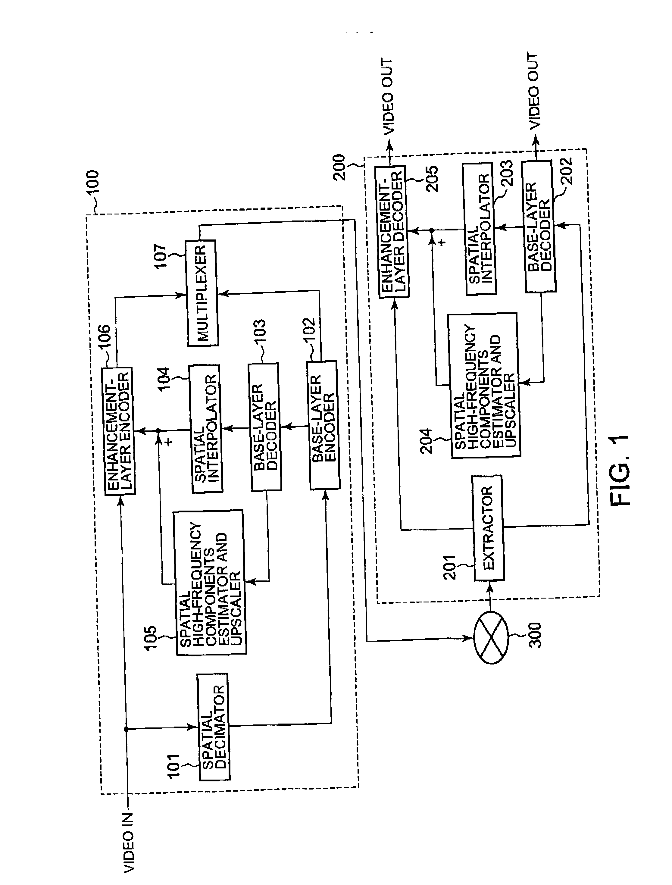
[0030] Shown in FIG. 1 are block diagrams of a layered coding apparatus 100 and a layered decoding apparatus 200.

[0031] The layered coding apparatus 100 is electrically connected to the layered decoding apparatus 200 via a transfer cable or other media 300. Input to the layered coding apparatus 100 is a video signal carrying moving pictures. The video signal is subjected to a coding procedure at the coding apparatus 100.

[0032] Output from the layered coding apparatus 100 is a bitstream which is then supplied to the layered decoding apparatus 200 via the transfer cable or media 300....


PUM


Abstract

An input video signal is encoded at a plurality of coding layers exhibiting different spatial resolutions. Decoded is a given signal coded at a lower coding layer lower than a specific coding layer among the plurality of coding layers to generate a decoded signal of the lower coding layer. Spatial interpolation is applied to the decoded signal of the lower coding layer to generate an upscaled decoded video signal. The spatial interpolation is an upscaling procedure to upscale the decoded signal of the lower coding layer into a spatial resolution of the specific coding layer. A spatial high-frequency components estimation and scale up procedure is applied to the decoded signal of the lower coding layer to generate a high-frequency components signal. The upscaled decoded video signal and the high-frequency components signal are subtracted from the input video signal exhibiting a spatial resolution of the specific coding layer to produce a predictive-error signal. Then, the predictive-error signal is encoded at the specific coding layer to generate an output bitstream. The decoding, spatial interpolating, spatial high-frequency components estimating and upscaling, and encoding procedures are executed at, at least, the specific coding layer among the plurality of coding layers except the lowest coding layer exhibiting the lowest spatial resolution thereamong.

Description

CROSS-REFERENCE TO RELATED APPLICATIONS [0001] This application is based on and claims the benefit of priority from the prior Japanese Patent Application Nos. 2005-341502 filed on Nov. 28, 2005 and 2006-317155 filed on Nov. 24, 2006, the entire contents of which are incorporated herein by reference. BACKGROUND OF THE INVENTION [0002] The present invention relates to layered coding and decoding methods, apparatuses, and programs for moving pictures based on spatial- and time-domain and also interlayer correlation. [0003] Several spatial- and time-domain resolution and SNR (Signal-to-Noise) scalable video coding schemes have been proposed and employed in a variety of fields. In particular, spatial-domain resolution scalable video coding schemes are most applicable to still and moving pictures. [0004] A spatial-domain resolution scalable layered video coding scheme produces interlayer predictive signals for use in coding enhancement layers that exhibit higher spatial resolutions than b...

Claims


Application Information

Patent Timeline
IPC IPC(8): H04N11/02H04N19/50H03M7/30H04N19/132H04N19/149H04N19/196H04N19/30H04N19/423H04N19/46H04N19/60H04N19/70H04N19/80H04N19/91
CPCH04N19/33H04N19/29
Inventor SAKAZUME, SATORUSHIMAUCHI, KAZUHIROKUMAKURA, TORUUEDA, MOTOHARU
Owner COMCAST CABLE COMM LLC
Why Eureka
Try Eureka