Francis pump-turbine

a pump-turbine and hydraulic technology, applied in vessel construction, renewable energy generation, greenhouse gas reduction, etc., can solve the problems of not solving the pump operation efficiency is decreasing, and the solution to the drift of the driving water cannot be found. achieve the effect of increasing the efficiency of partial load and preventing the backflow of the driving water

Active Publication Date: 2007-06-21
KK TOSHIBA
View PDF6 Cites 3 Cited by
  • Summary
  • Abstract
  • Description
  • Claims
  • Application Information

AI Technical Summary

Benefits of technology

[0020] The invention was conceived in consideration of the circumstances mentioned above and an object of the present invention is to provide a Francis pump-turbin

Problems solved by technology

This method, however, has induced backflow to the runner blades 8 during the operation of the pump, extremely decreasing pump operation efficiency.
However, it provides no solution to the drift of the driving water when the turbine is in operation.
On the other hand, the technique proposed in FIG. 14 does not solve the pr

Method used


Image

  • Francis pump-turbine
  • Francis pump-turbine
  • Francis pump-turbine

Examples


first embodiment

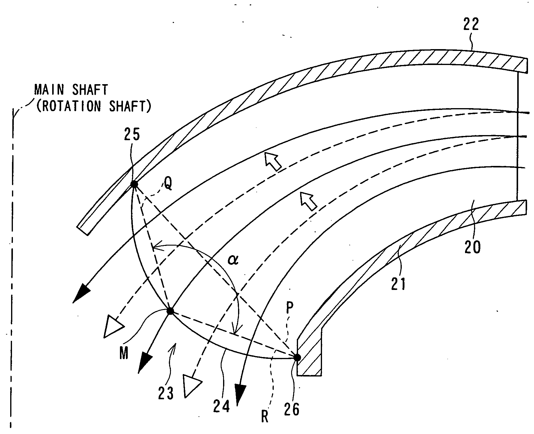
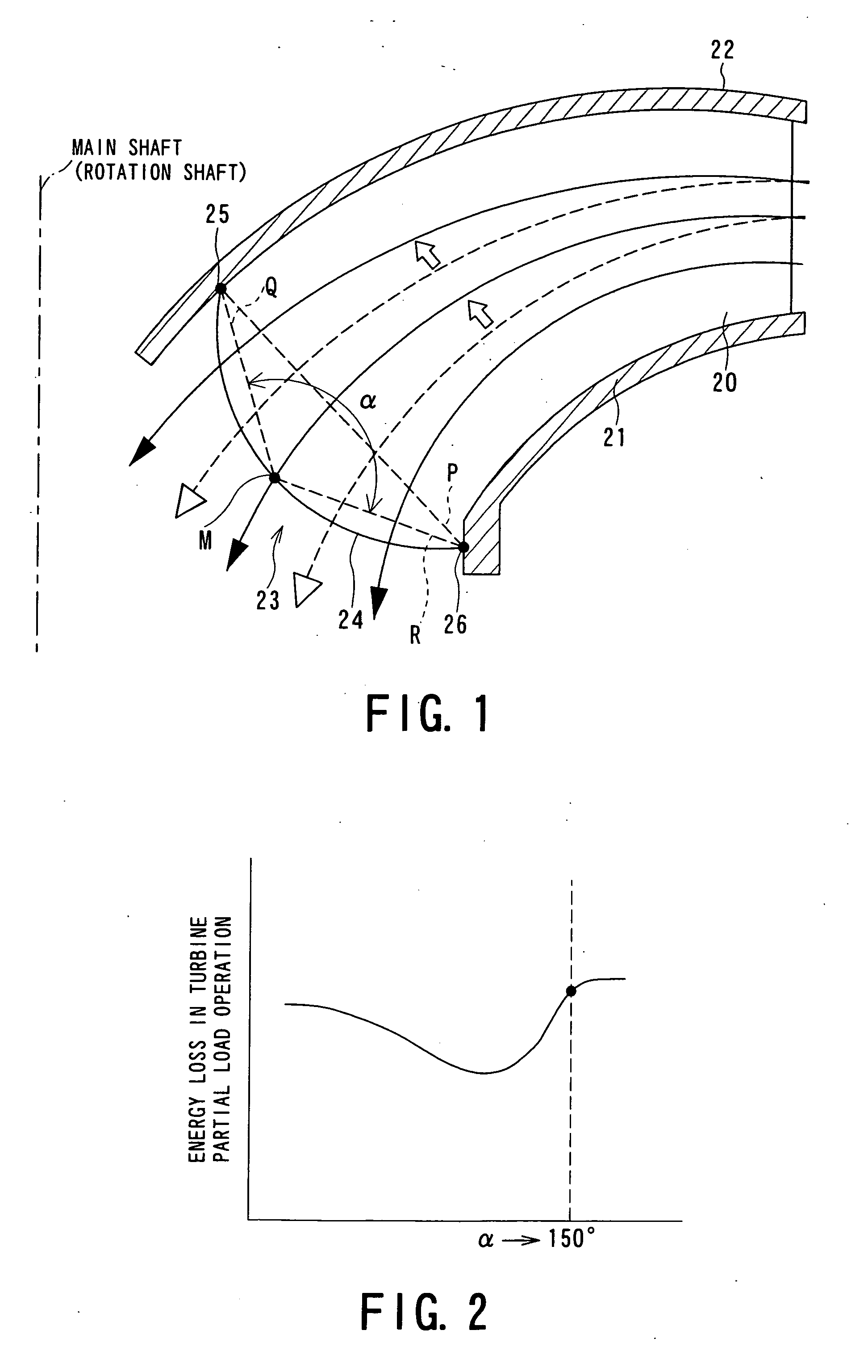
[0053]FIG. 1 shows an essential portion of a Francis pump-turbine according to the invention.

[0054] The Francis pump-turbine according to this first embodiment is constructed such that a trailing edge 23 of each of runner blades 20 bulges out toward a main shaft (i.e., rotational shaft) so as to form a curved portion 24 when the turbine is in operation (on the other hand, when the pump is in operation, a leading edge bulges), the runner blade 20 being supported at its bottom side by a band 21 in a blade height direction and supported at the head by a crown 22. The curved portion 24 has a maximum point M with respect to a straight line P connecting a crown-side trailing edge connecting end 25 at which the trailing edge 23 and the crown 22 are connected and a band-side trailing edge connecting end 26 at which the trailing edge 23 and the band 21 are connected, and the curved portion 24 also has an angle a formed by a straight line Q connecting the maximum point M and the crown-side tr...

third embodiment

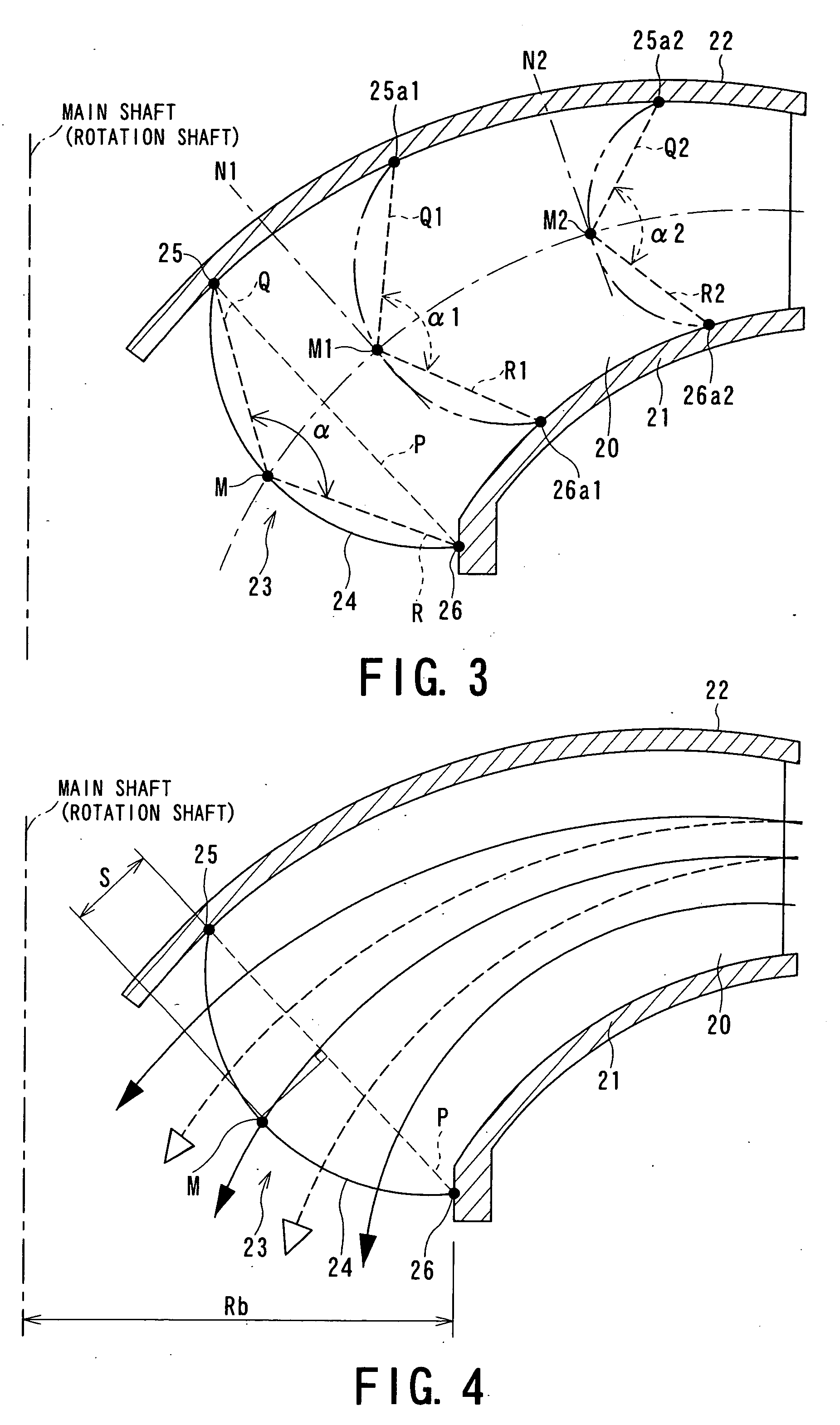
[0062]FIG. 4 is a conceptual diagram of an essential portion of a Francis pump-turbine according to the invention.

[0063] The Francis pump-turbine according to this third embodiment is constructed such that the trailing edge 23 of each runner blade 20 when the turbine is in operation (while, the leading edge when the pump is in operation) bulges out toward the main shaft to form the curved portion 24, the runner blade 20 being supported at its bottom portion by the band 21 in the blade height direction and supported at the head by the crown 22. The curved portion 24 has a maximum point M, and a distance ratio S / Rb is set to be within the range of S / Rb≧150°, where S is a distance between the maximum point M and the straight line P connecting the crown-side trailing edge connecting end 25 and the band-side trailing edge connecting end 26, and Rb is a distance between the main shaft and the band-side trailing edge connecting end 26.

[0064]FIG. 5 is a graph of energy loss obtained by exp...

fourth embodiment

[0069]FIGS. 6 and 7 are conceptual diagrams of a Francis pump-turbine according to the invention.

[0070] With reference to FIG. 6, the Francis pump-turbine according to this fourth embodiment has runner blades 20 supported by the band 21 and crown 22 and arranged along the circumferential direction of a main shaft (rotation shaft) 27, each having a leading edge (on the other hand, a trailing edge when the pump is in operation) 28 on the inner diameter side and having a trailing edge (on the other hand, a leading edge when the pump is in operation) 29 on the outer diameter side.

[0071] Referring to FIG. 7, in which the curvature radius R1 of a pressure surface 31 is set to be smaller than the curvature radius R2 of a suction surface 30, and there is set a minimum thickness of the runner blade 20 at a central portion in the height direction of the runner blade forming the curved portion 24.

[0072] That is, as shown in FIG. 7, the minimum thickness to at the center in the height directi...


PUM


Abstract

A Francis pump-turbine includes a runner provided with runner blades arranged around in a circumferential direction of a main shaft of the runner, each of the runner blades being supported by a band at a bottom side thereof in a blade height direction and supported by a crown at a head side in the blade height direction, in which the runner blade is formed, at a trailing edge thereof, with a curved portion expanding to the main shaft when the turbine is in operation, the curved portion has a maximum point with respect to a straight line connecting a crown-side trailing edge connecting end at which the trailing edge and the crown are connected and a band-side trailing edge connecting end at which the trailing edge and the band are connected, and an angle a formed by a straight line connecting the maximum point and the crown-side trailing edge connecting end and a straight line connecting the maximum point and the band-side trailing edge connecting end is set to be within a range of α≦150°.

Description

BACKGROUND OF THE INVENTION [0001] 1. Field of the Invention [0002] The present invention relates to Francis pump-turbines and, in particular, to a Francis pump-turbine capable of being operated at high-efficiency when the turbine is in a partial load operation. [0003] 2. Related Art [0004] General Francis pump-turbines can freely select either a generating mode or a pump mode by switching the rotation of a motor generator from normal rotation to reverse rotation or vice versa. [0005]FIG. 11 illustrates a general structure of a Francis pump-turbine, and as shown in FIG. 11, when the turbine generator is in operation, the Francis pump-turbine with this structure guides driving (operating) water, which is supplied from a high-level reservoir and a hydraulic pipe, both are not shown, to a spiral casing 1, to a runner 4 through a stay vane 2 and a guide vane 3 to rotate the runner 4, and supplies the power (running torque) generated at that time to a motor generator, not shown, via a ma...

Claims


Application Information

Patent Timeline
IPC IPC(8): B63H1/16
CPCF03B3/125Y02E10/223Y02E10/20
Inventor NAKAMURA, KAZUYUKITEZUKA, KOTAROKUROKAWA, TOSHIFUMI
Owner KK TOSHIBA
Why Eureka
Try Eureka