
Current damper for the study of cells

a current damper and cell technology, applied in the field of scientific devices, can solve the problems of limited utility of studies, affecting the study of cells, so as to prevent or reduce currents

Inactive Publication Date: 2007-06-21
SENG ENTERPRISES
View PDF99 Cites 32 Cited by
  • Summary
  • Abstract
  • Description
  • Claims
  • Application Information

AI Technical Summary

Benefits of technology

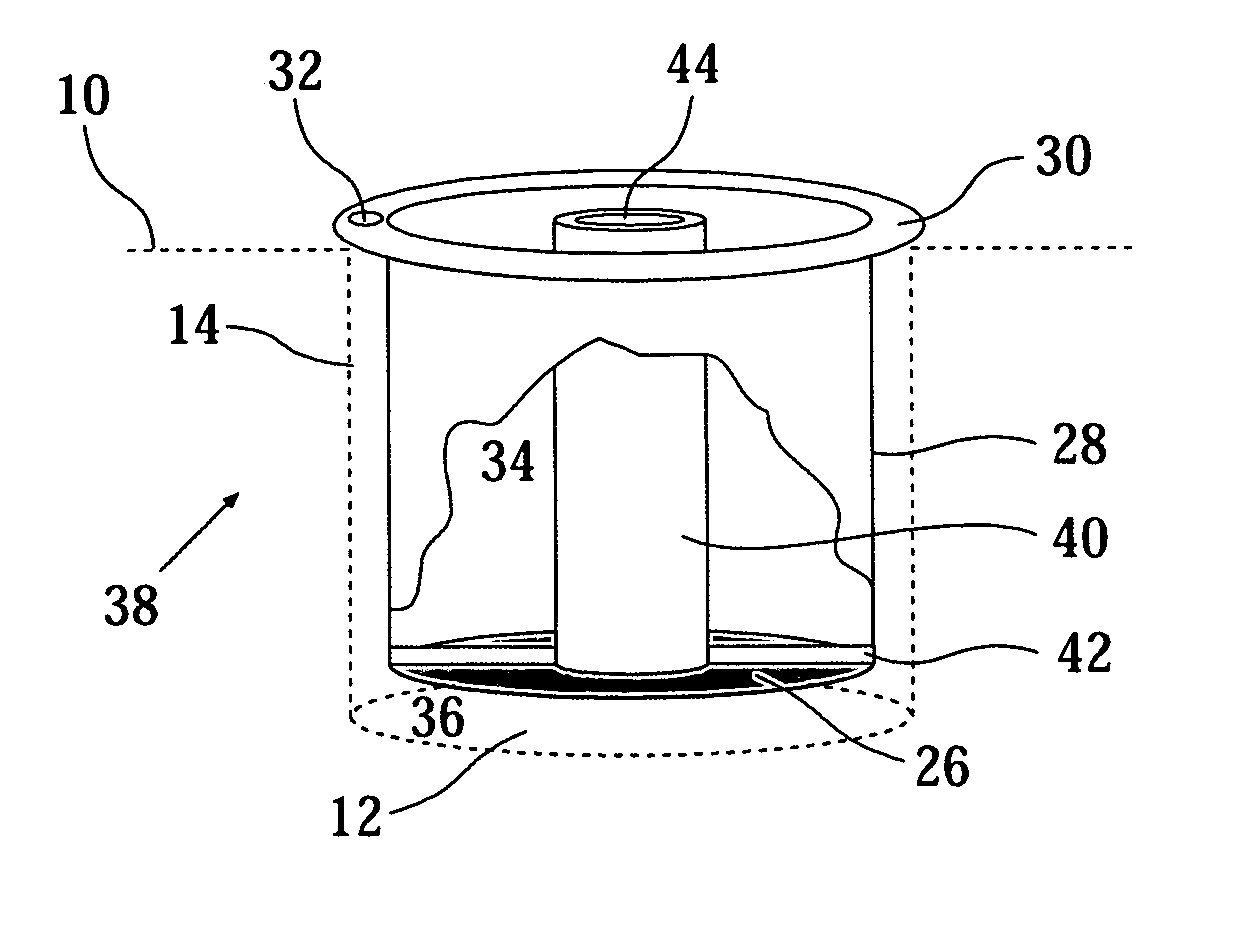
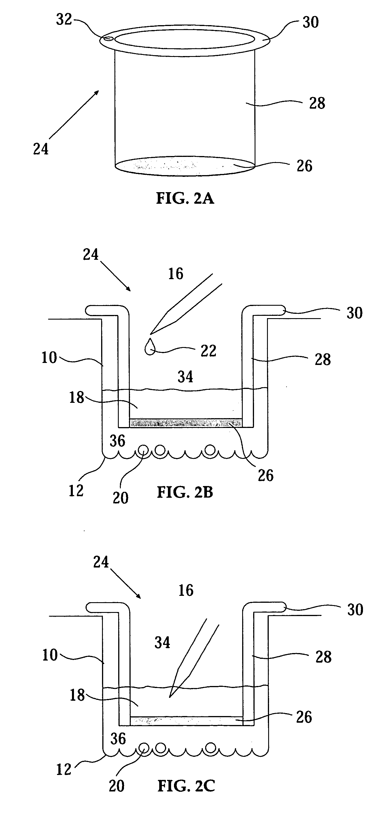
[0018] The present invention successfully addresses at least some of the shortcomings of the prior art by providing a damping component disposed within a cell-holding vessel, such as a microwell. When material (e.g., a fluid or solid) is added to the vessel or when a device (e.g., a probe or a detector) is placed in the vessel the damping component damps, that is to say, prevents or reduces currents, turbulence or flows that otherwise would cause cells held in the vessel, and especially resting on the bottom of the vessel, to move.
[0027] In embodiments of the present invention the damping surface is configured to be entirely submerged in a liquid held in the vessel. In such an embodiment a current damper is more effective in also damping currents cause by movement of the vessel.
[0059] In embodiments of the present invention, the damping surface is substantially entirely submerged in the liquid. The advantage of such an embodiment is that the damping component is then more effective at damping currents caused by movement of the vessel.

Problems solved by technology

Such studies are of limited utility due to the fact that naturally occuring cell populations are rarely homogenous and often it is the heterogenity and the differences of behavior of cells that is interesting.
Efforts have been made to use vessels having a planar bottom surface to study cells as individuals but such efforts are plagued with many difficulties.
A first difficulty is that cells have a tendency to clump together in variably sized groups at random locations, and often stack one on top of the other.
It is thus virtually impossible to identify which cell has a given behavior.
Further, the fact that cells are randomly distributed over a featureless surface makes it impossible to definitely differentiate one cell from another without continuous observation of the cell.
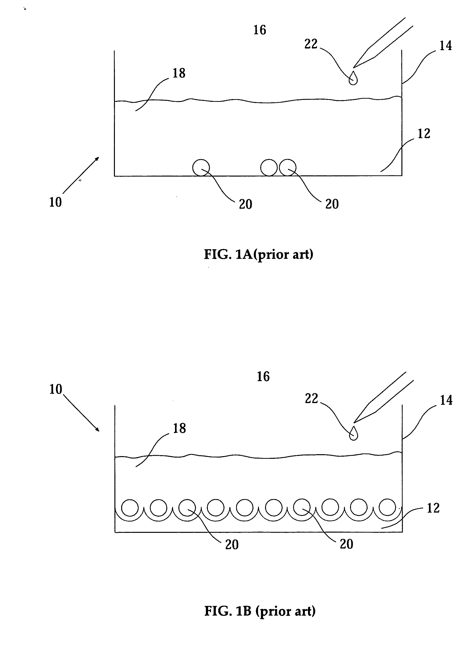
The greatest difficulty limiting the utility of such methods is that even the slightest current, whether caused by addition of a material to the vessel or by movement, e.g. incidental jostling, of the vessel causes the cells to move randomly leading to the loss of identity of the cells and rendering experiments difficult to perform, limited in scope and slow.
Many such devices bind or adhere to the surface of the cells or deform the shape of the cells, adversely effecting the results of performed studies, see for example Mrksich and Whitesides, Ann. Rev. Biophys. Biomol. Struct. 1996, 25, 55-78; Craighead et al., J. Vac. Sci. Technol.
A first disadvantage is the need for for flow generators and concomitant interfaces that increases the complexity of such devices.
A second disadvantage is that the difficulties in the use of the device including loading, attaching flow generators and the like render the integration of such a device with a robotics system for automatised use impractical.
Although extremely useful, the device taught in PCT patent application PCT / IL2005 / 000801 does not provide a general solution allowing the use of existing vessels for the study of cells.
Unfortunately under certain conditions currents in a liquid held in a well may cause cells held in picowells to move and thus lose identity.

Method used


Image

  • Current damper for the study of cells
  • Current damper for the study of cells
  • Current damper for the study of cells

Examples


Embodiment Construction

[0092] The present invention is of a device for the study of cells comprising a vessel for holding cells, where the cells rest on the bottom surface of the vessel, and a current damper including a damping component substantially disposed within the vessel. The present invention is also of a current damper configured to be placed in, or disposed within, a vessel. The present invention is also of a method for using a device of the present invention. While a cell or cells are resting on the bottom surface of the vessel a material (e.g., a liquid or solid reagent) is added to the vessel or a device (e.g., a probe or a detector) is placed in the vessel. The damping component preferably damps currents caused by the addition of the material or the placement of the device that would otherwise cause movement of the cell or cells. The damping component preferably also damps currents caused by movement of the vessel that would otherwise cause movement of the cell or cells.

[0093] The principle...


PUM


Abstract

A device for the study of cells including a vessel with a current damper including a damping component substantially disposed within the vessel is disclosed. The damping component reduces or eliminates currents formed by the addition of materials such as liquids to the vessel to prevent the movement of cells resting on the bottom surface of the vessel.

Description

RELATED APPLICATIONS [0001] This application is a Continuation-In-Part (CIP) Application of PCT Application No. PCT / IL2005 / 001078, filed on Oct. 11, 2005, which claims priority from U.S. Provisional Patent Application No. 60 / 618,999, filed on Oct. 18, 2004, U.S. Provisional Patent Application No. 60 / 637,752, filed on Dec. 22, 2004, and U.S. Provisional Patent Application No. 60 / 686,440, filed on Jun. 2, 2005. [0002] This application also claims priority from U.S. Provisional Patent Application No. 60 / 754,195, filed on Dec. 28, 2005, and U.S. Provisional Patent Application No. 60 / 855,173, filed on Oct. 30, 2006. [0003] The contents of the above Applications are all incorporated herein by reference.FIELD AND BACKGROUND OF THE INVENTION [0004] The present invention relates to the field of scientific devices and more particularly, to an improved device for the study of cells. Specifically, the present invention is of a device allowing the addition of a material to a vessel without distu...

Claims


Application Information

Patent Timeline
IPC IPC(8): C12M1/34C12M3/00
CPCC12M23/10C12M23/56C12M29/04C12M33/00B01L3/50255B01L3/5085B01L2300/0829B01L2300/0851B01L2400/086C12M23/12C12M25/04
Inventor DEUTSCH, MORDECHAI
Owner SENG ENTERPRISES
Learn More