Electrical terminal

Inactive Publication Date: 2007-06-21
PHOENIX CONTACT GMBH & CO KG
View PDF6 Cites 14 Cited by
  • Summary
  • Abstract
  • Description
  • Claims
  • Application Information

AI Technical Summary

Benefits of technology

[0010] An object of embodiments of this invention is to provide an electrical terminal that enables simple manual opening of the clamping site,

Problems solved by technology

However, since high current terminals must also be manually actuated for opening the clamping sites against the respective clamping force of the clamping terminal, maximization of the type of construction of conventional terminals is limited, since lead

Method used


Image

  • Electrical terminal
  • Electrical terminal
  • Electrical terminal

Examples


Embodiment Construction

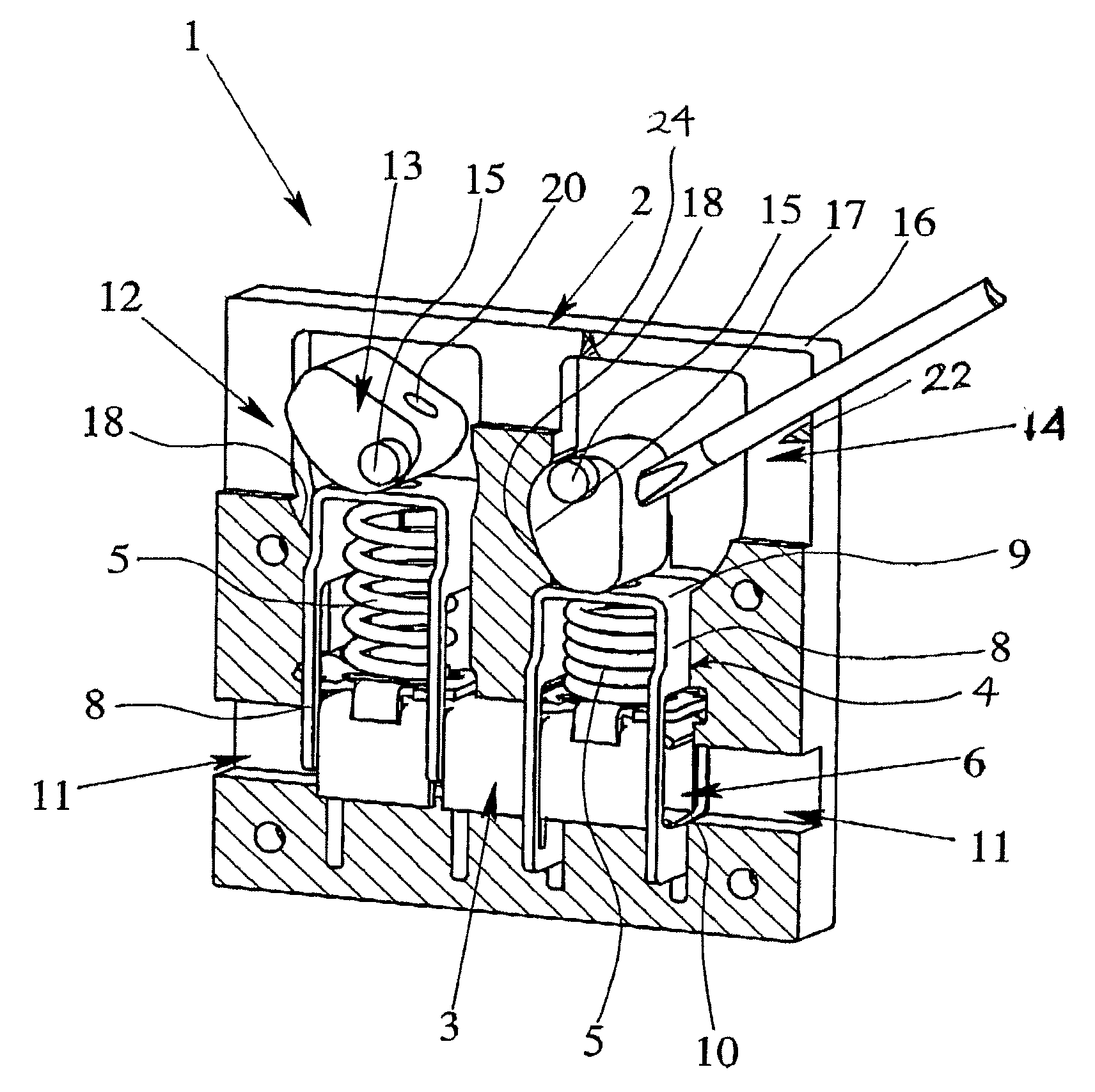
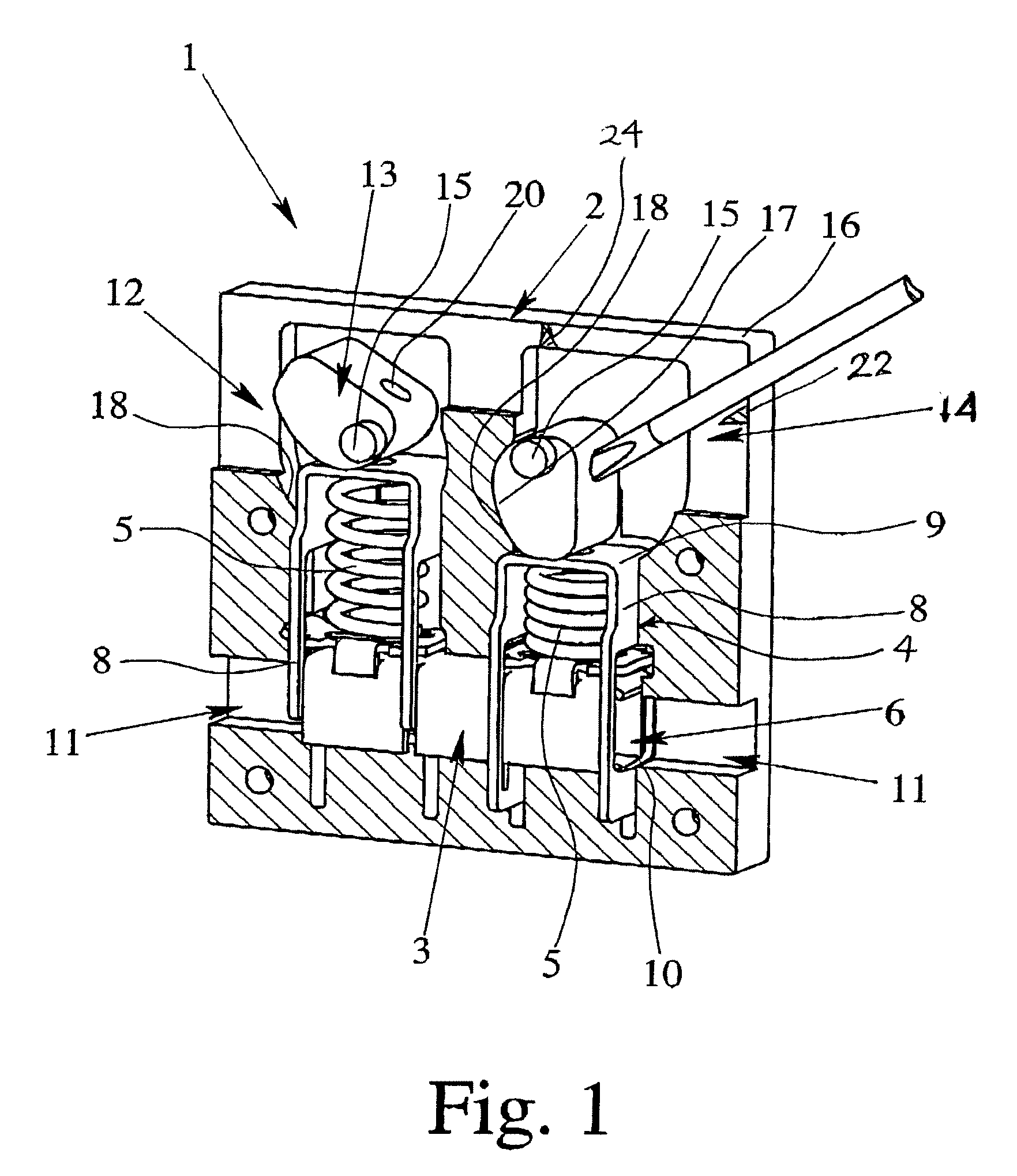
[0021]FIG. 1 shows an electrical terminal 1 with an insulating housing 2, a conductor bar 3 located in the insulating housing 2, and two strain-relief clamp connections. The two strain relief clamp connections each have a generally U-shaped strain-relief clamp 4 and a helical compression spring 5 located within the strain-relief clamp 4. As is especially apparent from FIGS. 2 and 3, the strain-relief clamp 4 has two clamping legs 8 that each have one through opening 6 for inserting an electric lead 7 to be electrically connected, and a U-shaped back 9 that connects the clamping legs 8 to one another. The conductor bar 3 is inserted into the through openings 6 of the strain-relief clamp 4 so that the through openings 6 surround the conductor bar 3.

[0022] The compression spring 5 is located between the U-shaped back 9 of the strain-relief clamp 4 and the conductor bar 3 such that the compression spring 5 pulls the lower edge 10 of the through opening 6 against the conductor bar 3, i....


PUM


Abstract

An electrical terminal includes an insulating housing, a conductor bar, strain-relief clamp connections and actuating elements located in the insulating housing for opening and closing the strain-relief clamp connections. The electrical terminal enables simple manual opening of the clamping site even when the strain-relief clamp connection is designed for leads with large cross section since the actuation element is made as an actuating cam that is eccentrically supported in the insulating housing. The actuating cam can be pivoted by an actuating tool out of a first position in which the strain-relief clamp connection is closed into a second position in which the strain-relief clamp connection is opened so that an electric lead can be inserted between the conductor bar and a through opening in the strain relief clamp connection.

Description

BACKGROUND OF THE INVENTION [0001] 1. Field of the Invention [0002] The invention relates to an electrical terminal, especially a high current terminal, with a strain relief device. [0003] 2. Description of Related Art [0004] Electrical terminals with contact elements made as tension springs, often called tension spring terminals, have been used for decades in industrial connection technology. In addition, electrical terminals with a screw-type terminal have been used for decades. The clamping principle for tension spring terminals is similar to that of screw technology. While in screw-type terminals a tension sleeve pulls the lead against a conductor bar by actuating the clamping screw, for a tension spring terminal this task can be assumed by a tension spring bent into a loop shape. The pretensioned tension spring is opened with an actuating tool, such as a screwdriver, so that the lead can be inserted into a through opening in the clamping leg of the tension spring into the termi...

Claims


Application Information

Patent Timeline
IPC IPC(8): H01R9/03
CPCH01R4/4872H01R4/489H01R4/5008H01R9/26
Inventor CAMINO, MANUELBRAND, JUERGENSCHULTE, HANS HILMAR
Owner PHOENIX CONTACT GMBH & CO KG
Why Eureka
Try Eureka