Oxidation protected blade and method of manufacturing

a technology of oxidation protection and blades, which is applied in the direction of coating, mechanical equipment, metallic material coating processes, etc., can solve the problems of reducing and affecting the efficiency of the engin

Inactive Publication Date: 2007-06-21
PRATT & WHITNEY CANADA CORP
View PDF42 Cites 8 Cited by
  • Summary
  • Abstract
  • Description
  • Claims
  • Application Information

AI Technical Summary

Problems solved by technology

A distortion or misalignment may cause a localized rub between a shroud segment and all blades.
Without an abradable system, this may leave a relatively large gap around the periphery of the rotor and reduce the efficiency of the engine.
The exposed areas will then be prone to oxidation.
Oxidation is particularly severe at the edge of the pressure side of blades This ultimately results in a premature wear of the blades.

Method used


Image

  • Oxidation protected blade and method of manufacturing
  • Oxidation protected blade and method of manufacturing
  • Oxidation protected blade and method of manufacturing

Examples


Embodiment Construction

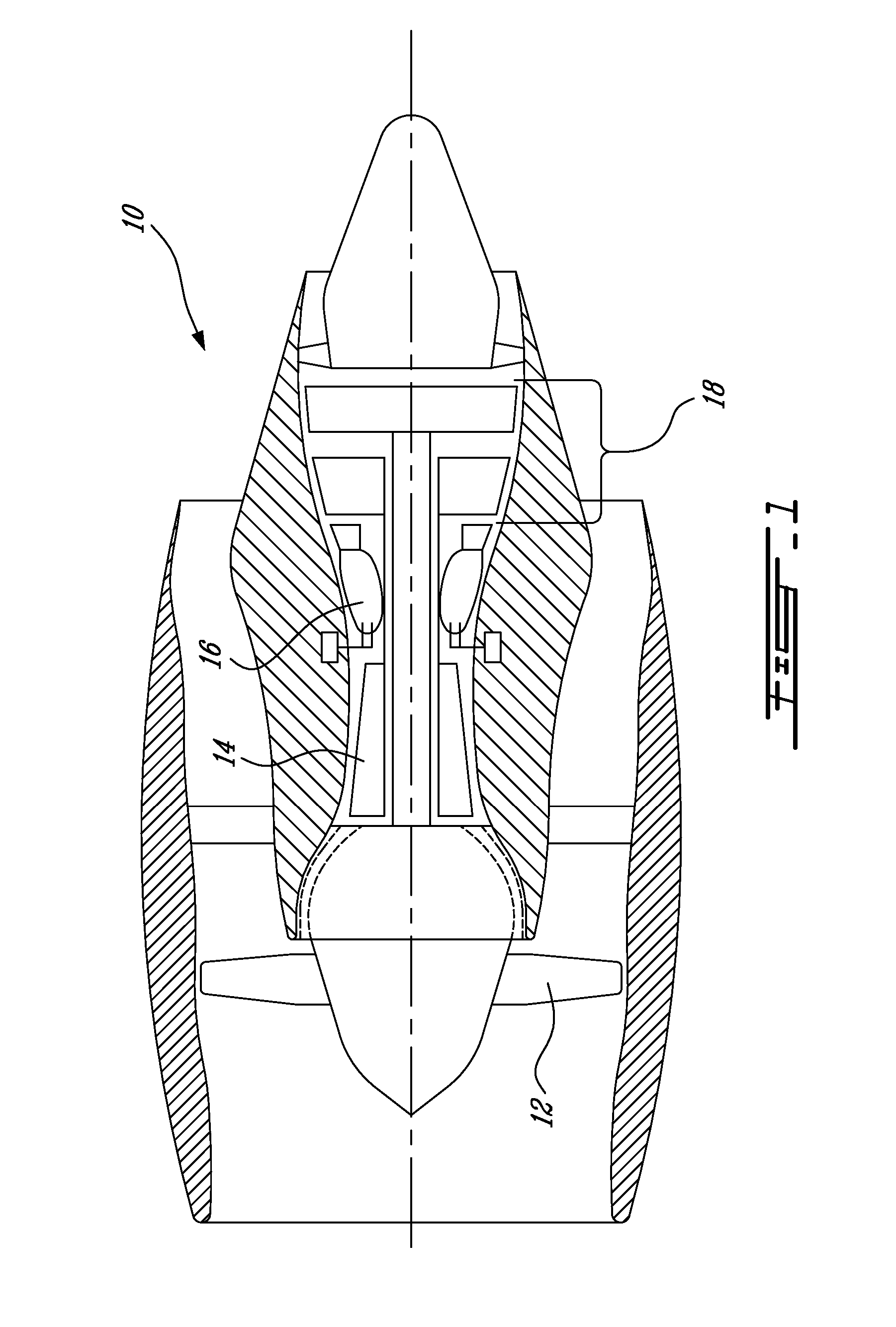
[0012]FIG. 1 illustrates a gas turbine engine 10 of a type preferably provided for use in subsonic flight, generally comprising in serial flow communication a fan 12 through which ambient air is propelled, a multistage compressor 14 for pressurizing the air, a combustor 16 in which the compressed air is mixed with fuel and ignited for generating an annular stream of hot combustion gases, and a turbine section 18 for extracting energy from the combustion gases. This figure shows one possible environment in which blades with oxidation protection can be used. It should be noted at this point that the invention is equally applicable to other kinds of gas turbine engines, such as turbo shafts or turbo props.

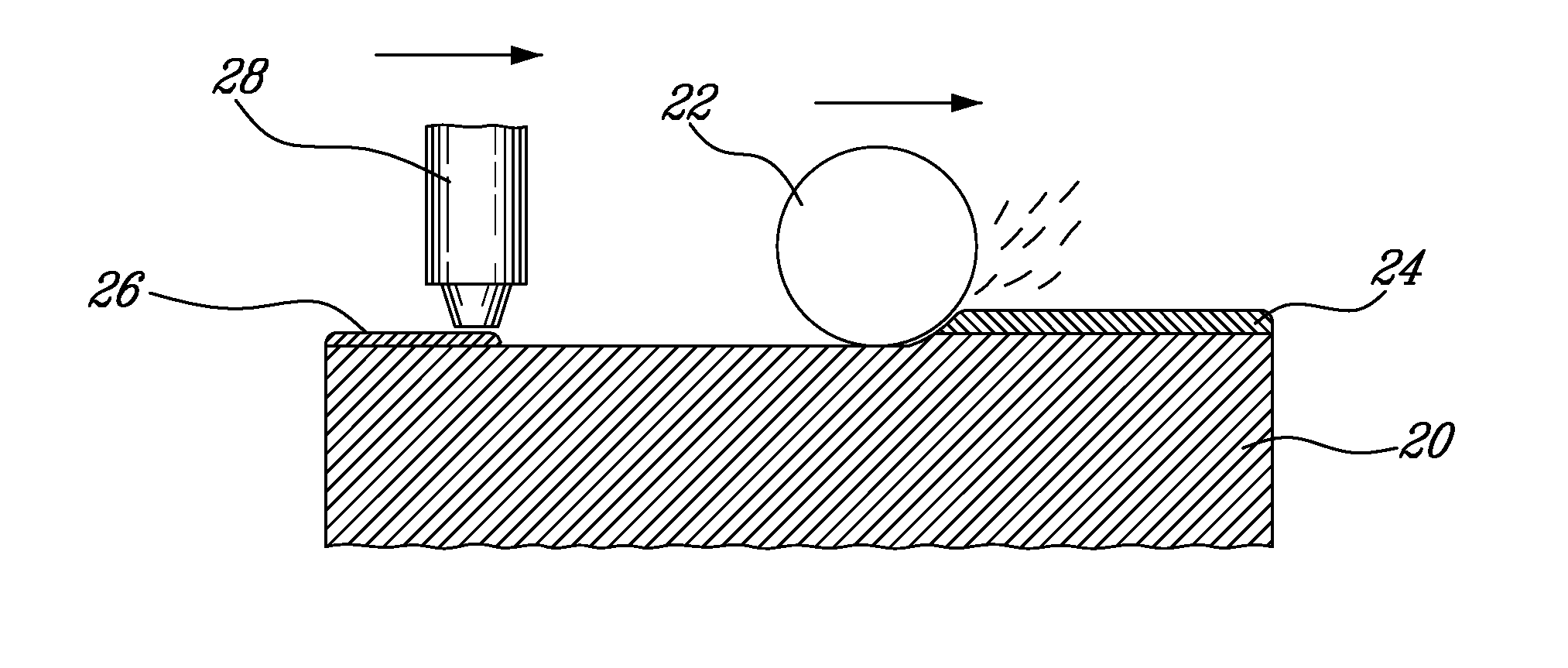
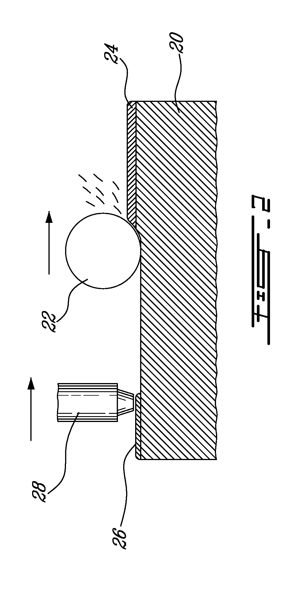
[0013]FIG. 2 schematically shows a surface of a blade 20 being manufactured in accordance with the present invention. It shows that material is removed from the surface using a material-removing tool, for instance a grinder 22. If the grinder 22 removes more material than the thickne...


PUM

PropertyMeasurementUnit
tip clearance dimensionaaaaaaaaaa
pressureaaaaaaaaaa
tip clearance heightaaaaaaaaaa

Abstract

The surface of a gas turbine blade is machined with a material-removing tool and simultaneously, an anti-oxidation coating is deposited on the surface using eletrospark deposition.

Description

CROSS-REFERENCE TO RELATED U.S. APPLICATION [0001] The present application is a continuation of U.S. patent application Ser. No. 11 / 231,829 filed Sep. 24, 2005, which application is hereby incorporated by reference.TECHNICAL FIELD [0002] The field of invention relates generally to the protection of blades in a gas turbine engine and, more particularly, to a blade provided with an oxidation protection layer and a method of manufacturing the same. BACKGROUND OF THE ART [0003] In small gas turbine engines, the shrouds located around the turbine blades are generally not provided with a layer of abradable material, as is the case for some larger engines. Reasons for this include the facts that large engines may have more carcass distortions and more misalignment between centerlines of the rotor and shrouds. A distortion or misalignment may cause a localized rub between a shroud segment and all blades. Without an abradable system, this may leave a relatively large gap around the periphery...

Claims


Application Information

Patent Timeline
Patent Type & Authority Applications(United States)
IPC IPC(8): B24B1/00
CPCC23C26/00F01D5/288F05D2230/90Y10T29/49316F05D2230/80F05D2230/10F05D2230/31F05D2300/611
Inventor JUNEAU, ALANLECUYER, DANLELBOUTHILLIER, ALAN
Owner PRATT & WHITNEY CANADA CORP
Why Eureka
Try Eureka