Multi-user adaptive array receiver and method

a multi-user, adaptive array technology, applied in diversity/multi-antenna systems, transmission monitoring, multiplex communication, etc., can solve the problems of limited ability against intersymbol interference (isi), limited ability against cci, and mean-square error, so as to reduce complexity and cost

Inactive Publication Date: 2007-06-21
UNIV LAVAL
View PDF12 Cites 84 Cited by
  • Summary
  • Abstract
  • Description
  • Claims
  • Application Information

AI Technical Summary

Benefits of technology

[0033] The present invention seeks to at least mitigate the disadvantages of such known array receiver systems and to this end provides a multiuser space-time array receiver, and system incorporating same, exploiting multiuser information in order to reduce complexity and cost.

Problems solved by technology

One of the most common error measures in such applications (i.e. adaptive filtering) is the mean-square error
However, it has limited ability against intersymbol interference (ISI) due to dispersive, i.e. frequency-selective, fading, since the latter is spread in time.
On the other hand, the equalizer is adept at combatting ISI but has limited ability against CCI.
One of the main disadvantages of previously-known space-time processing receivers is their great complexity and cost, especially if multiuser detection is employed and / or temporal processing employed.
It is known to reduce bandwidth requirements in forward-channel probing transmitters by tracking only long-term variations in the channels (i.e., the subspace structure) [11] but that approach is not applicable in receivers without seriously limiting user capacity.

Method used


Image

  • Multi-user adaptive array receiver and method
  • Multi-user adaptive array receiver and method
  • Multi-user adaptive array receiver and method

Examples


Embodiment Construction

[0077] To facilitate understanding of the construction and operation of the preferred ebodiments, some basic theory will first be presented.

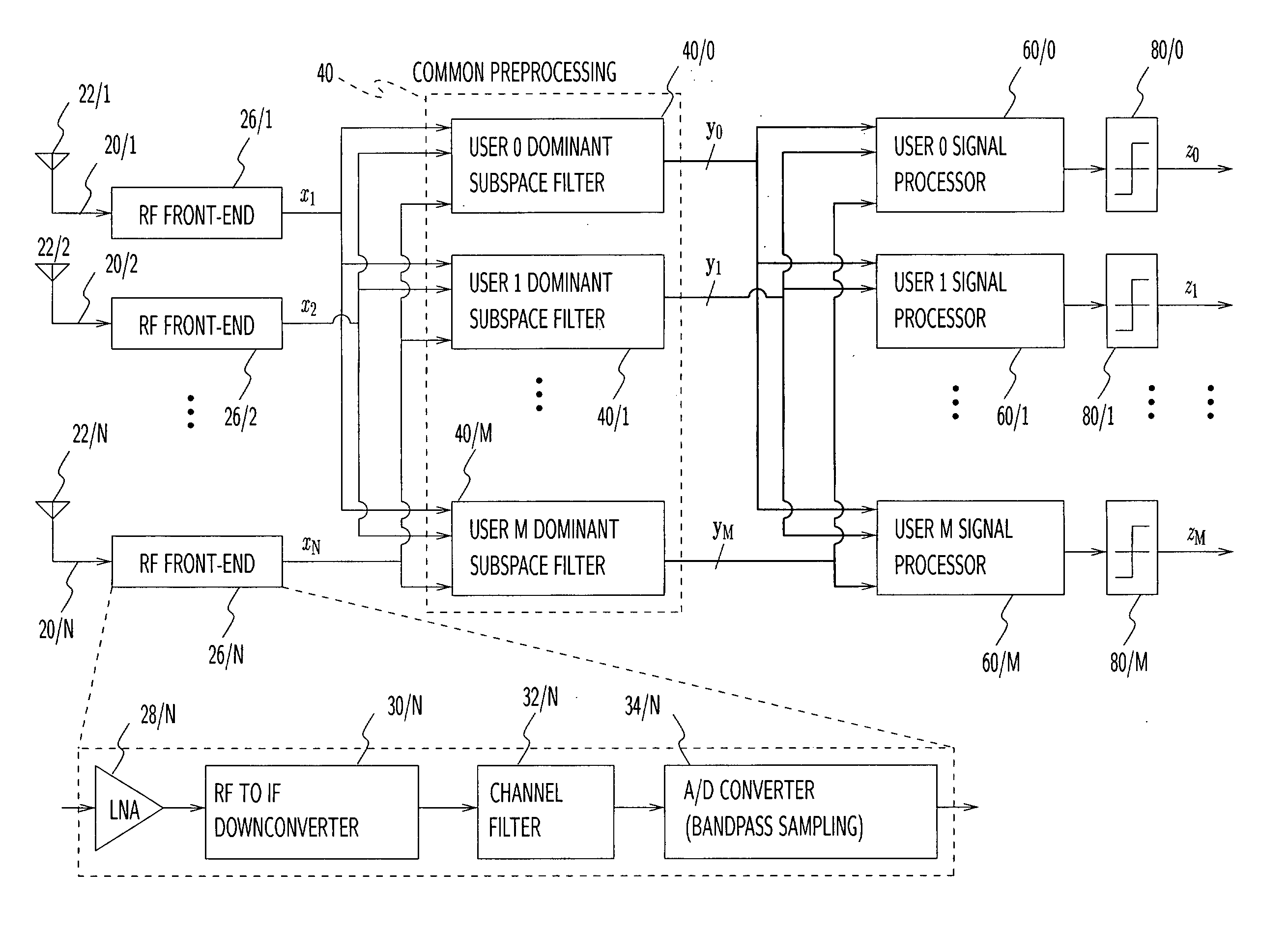
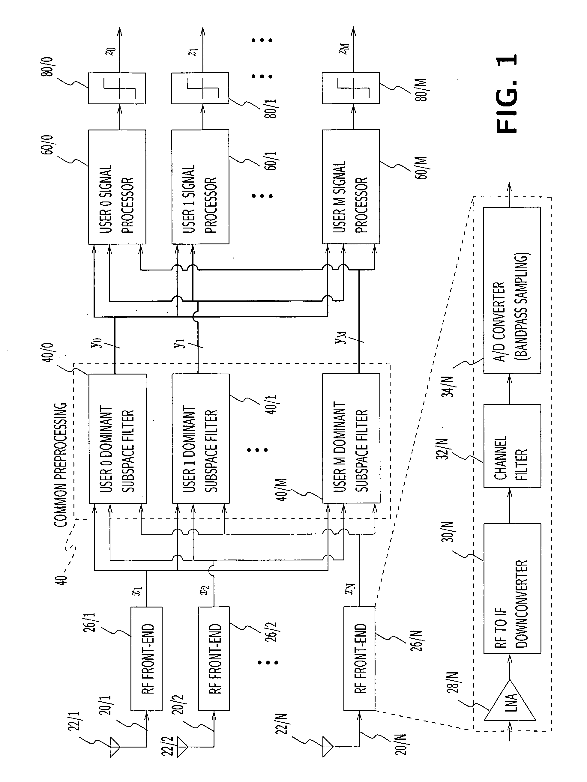
[0078] As discussed, the optimal MMSE solution can be obtained through a linear combination of all signals' matched-filters [7], [8]. Given an antenna array and a dispersive (i.e. ISI-inducing) propagation environment, it follows that the optimal MMSE solution can be obtained as a linear combination of all signals' space-time matched-filters. Here, a space-time filter matched to a given signal is a bank of N temporal filters, each of which processes one of the N antenna elements' outputs, and whose outputs are combined to maximize the said signal's power with respect to white noise and disregarding interference from the other man-made signals.

[0079] This is advantageous in a multi-user SDMA context since the set of matched filters form a common basis which can be reused to obtain each signal's MMSE solution. In standard optimal architectures, ...


PUM


Abstract

An array receiver which reduces complexity and cost by exploiting multiuser information in signals received from a plurality of transmitting users preprocesses (40) samples of antenna signals ( x1, x2 . . . , xN) from the antenna elements (22 / 1, . . . , 22 / N) to form basis signals (yO . . . , yM) together having fewer space-time dimensions than the space-time dimensions of the combined antenna signals. The receiver processes and combines the basis signals to produce sets of estimated received signals (z0, . . . , zM), each for a corresponding one of the users. Each of the basis signals comprises a different combination of the antenna signals. The receiver combines the basis signals to provide a user-specific output signal, and periodically updates parameters of the filters (40 / 0, . . . , 40 / M) used for deriving each particular basis signal such that each user-specific output signal will exhibit a desired optimized concentration of energy of that user's received signal as received by the array antenna.

Description

TECHNICAL FIELD [0001] The invention relates to a receiver system comprising an antenna and a receiver, the antenna comprising an array of antenna elements. It also relates to the receiver per se and to a receiving method. The invention is especially, but not exclusively, applicable to array receivers and methods for use in base stations of digital cellular telecommunications networks or access points of wireless local area networks (LANs). BACKGROUND ART [0002] The invention is applicable in systems wherein multiple users simultaneously make use of a common carrier or use distinct carriers with some amount of overlap / crosstalk between them such as (i) carrier reuse-within-cell (RWC), also called Space-Division Multiple Access (SDMA) because of the need for an antenna array to spatially discriminate co-channel signals; (ii) Code-Division Multiple Access (CDMA) systems where multiple users transmit in the same band using distinct codes; and (iii) Time-Division Multiple Access (TDMA) ...

Claims


Application Information

Patent Timeline
Patent Type & Authority Applications(United States)
IPC IPC(8): H04B7/08H04B1/06H04M1/00H04J99/00H04L1/06
CPCH04B7/0848H04B7/0851H04B7/0854H04L1/0618H04B7/0871
Inventor ROY, SEBASTIEN JOSEPH ARMAND
Owner UNIV LAVAL
Why Eureka
Try Eureka