Methods and apparatus for treating disc herniation and preventing the extrusion of interbody bone graft

a technology of disc herniation and interbody bone graft, which is applied in the field of methods, can solve problems such as further complications, and achieve the effect of avoiding delicate surrounding nerves and minimizing the size of the requisite incision

Inactive Publication Date: 2007-06-21
ANOVA
View PDF27 Cites 34 Cited by
  • Summary
  • Abstract
  • Description
  • Claims
  • Application Information

AI Technical Summary

Benefits of technology

[0008] The device is preferably collapsible into some form for the purposes of insertion, thereby minimizing the size of the requisite incision while avoiding delicate surrounding nerves. Such a configuration also permits the use of instrumentation to install the device, including, for example, a hollow tube and a push rod to expel the device or liquefied material out of the sheath for use in occluding the disc defect.
[0009] A device according to the invention may further include one or more anchors to assist in permanently affixing the device with respect to the defect. For example, in the embodiment of a mesh screen, the anchors may assume the form of peripheral hooks configured to engage with the vertebra on either side of the disc. The invention further contemplates a distracting tool used to force the anchors into the vertebra. Such a tool would preferably feature a distal head portion conformal to the expanded shape of the device, enabling the surgeon to exert force on the overall structure, thereby setting the anchors.

Problems solved by technology

This results in pain and further complications, in many cases.

Method used


Image

  • Methods and apparatus for treating disc herniation and preventing the extrusion of interbody bone graft
  • Methods and apparatus for treating disc herniation and preventing the extrusion of interbody bone graft
  • Methods and apparatus for treating disc herniation and preventing the extrusion of interbody bone graft

Examples


Embodiment Construction

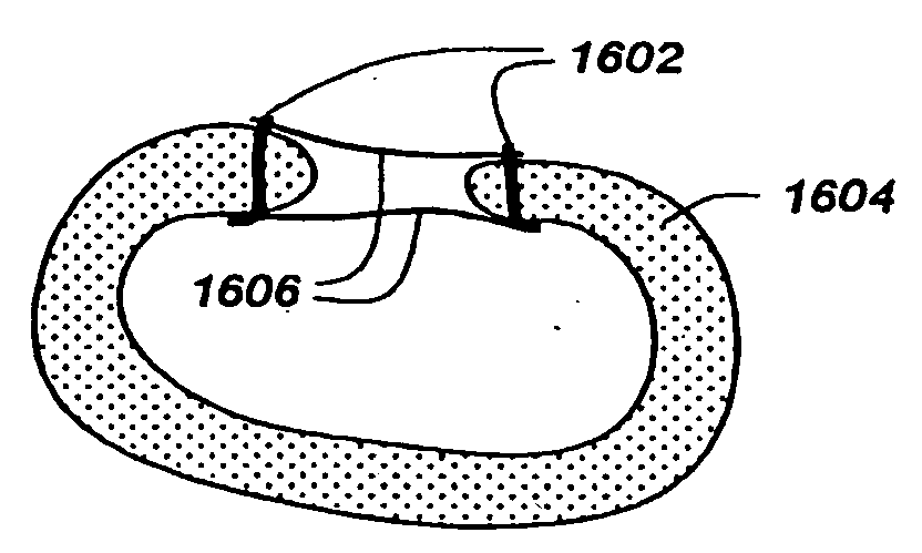
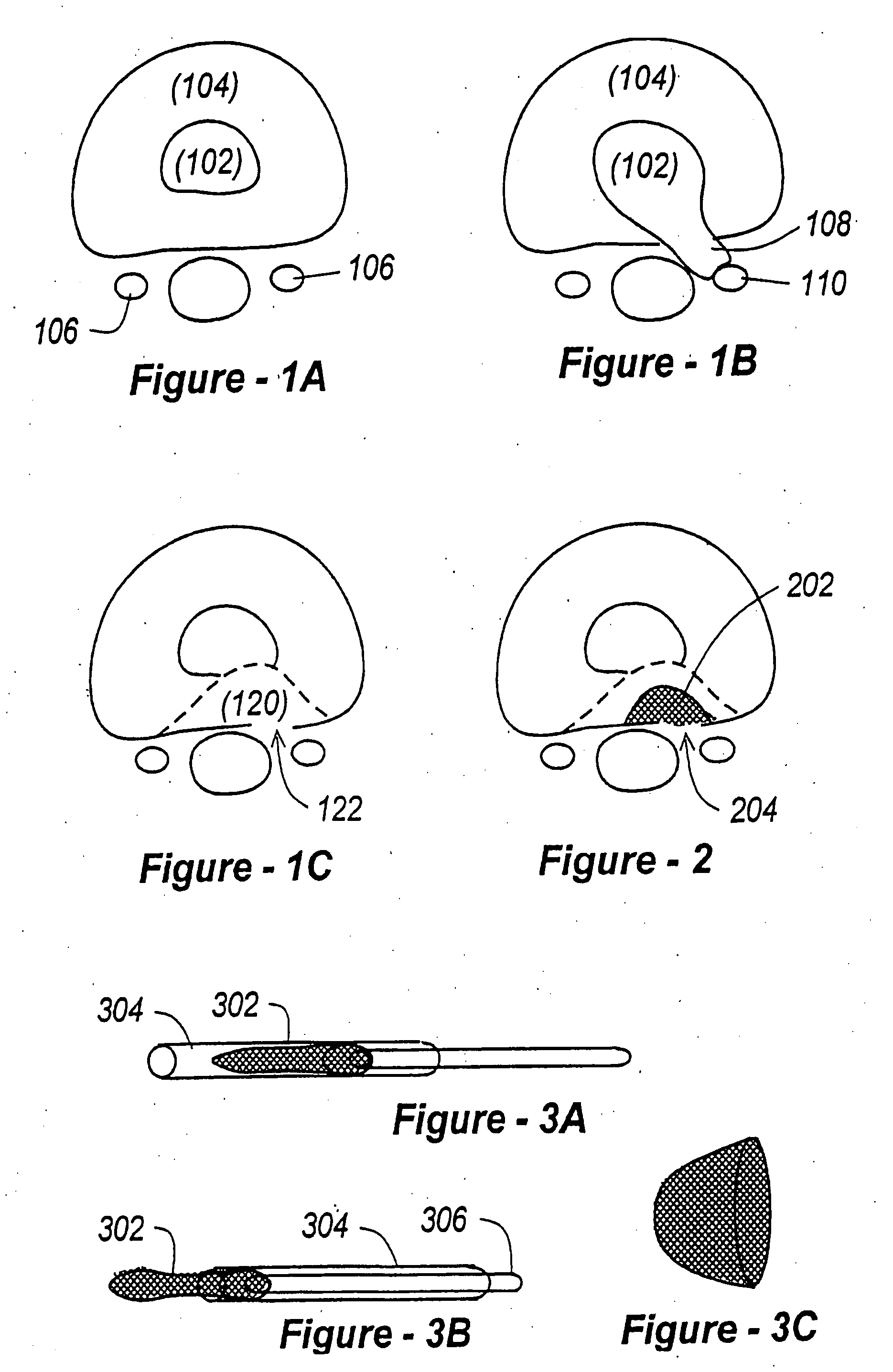
[0076] Having discussed the problems associated with post-operative partial discectomy with respect to FIG. 1A-1C, reference will now be made to FIG. 2, which illustrates a preferred embodiment of the invention, wherein a device in the form of a stent 202 is used to occlude a defect 204 in a human disc, as shown. In this preferred embodiment, the device is composed of a flexible material, which may be cloth, polymeric or metallic. For reasons discussed below, a titanium mesh screen is preferred with respect to this embodiment of the invention.

[0077] A flexible device is also preferred because the surgeon is presented with a very small working area. The incision through the skin is typically on the order of 1 to 1.5 inches in length, and the space at the disc level is approximately 1 centimeter on the side. As a consequence, the inventive device and the tools associated with insertion and fixation described below must be sufficiently narrow to fit within these confines.

[0078] As sh...


PUM

PropertyMeasurementUnit
lengthaaaaaaaaaa
lengthaaaaaaaaaa
sizeaaaaaaaaaa

Abstract

Methods and apparatus for treating defects in the annulus fibrosis are described. The methods include providing first and second elongate fastening members, each having a first end and an anchor on the first end that is substantially transverse when deployed. The first end of the first and second elongate fastening members are positioned distal of the outer layer and at least one inner layer of the annulus fibrosis. The defect is then closed by interlocking the first and second elongate fastening members. Alternatively, second ends of the elongate fastening members may be linked, resulting in reducing the size of the opening of the defect. Devices having first and second elongate fastening members, each having a first end, a second end, and an anchor on the first end that is substantially transverse when deployed; and a connector that links the first and second elongate fastening members are also described.

Description

REFERENCE TO RELATED APPLICATIONS [0001] This is a continuation of U.S. patent application Ser. No. 10 / 630,445, filed Jul. 30, 2003, which is a continuation of U.S. patent application Ser. No. 09 / 638,241, filed Aug. 14, 2000, which is a continuation-in-part of International Patent Application No. PCT / US00 / 14708, filed May 30, 2000. The '241 application also claims priority from U.S. Provisional Patent Application Ser. No. 60 / 148,913, filed Aug. 13, 1999. The entire content of each application and patent is expressly incorporated herein by reference in its entirety.FIELD OF THE INVENTION [0002] This invention relates generally to the prosthetic appliances and, in particular, to devices for occluding intervertebral disc defects and instrumentation associated with introducing such devices. BACKGROUND OF THE INVENTION [0003] Several hundred thousand patients undergo disc operations each year. Approximately five percent of these patients will suffer recurrent disc herniation, which resul...

Claims


Application Information

Patent Timeline
Patent Type & Authority Applications(United States)
IPC IPC(8): A61F2/30A61B17/00A61B17/02A61B17/16A61F2/00A61F2/02A61F2/28A61F2/44A61F2/46A61L27/38
CPCA61B17/1671A61B2017/00261A61B2017/0256A61F2/2846A61F2/30742A61F2/30744A61F2/30965A61F2/441A61F2/442A61F2/4455A61F2/447A61F2/4601A61F2/4611A61F2002/2835A61F2002/30093A61F2002/30131A61F2002/30153A61F2002/302A61F2002/30224A61F2002/30235A61F2002/30271A61F2002/30283A61F2002/30329A61F2002/30433A61F2002/30441A61F2002/30461A61F2002/3052A61F2002/30538A61F2002/30556A61F2002/30565A61F2002/30576A61F2002/30579A61F2002/30589A61F2002/30626A61F2002/30677A61F2002/30774A61F2002/30777A61F2002/30784A61F2002/30787A61F2002/30828A61F2002/30909A61F2002/30975A61F2002/4435A61F2002/444A61F2002/4445A61F2002/445A61F2002/4475A61F2002/448A61F2002/4627A61F2002/4628A61F2210/0019A61F2220/0025A61F2220/0041A61F2220/0075A61F2230/0013A61F2230/0019A61F2230/0063A61F2230/0065A61F2230/0069A61F2230/0082A61F2250/0006A61F2250/0009A61F2250/0069A61F2310/00017A61F2310/00023A61F2310/00029A61L27/3856A61L2430/38A61F2002/30092A61F2002/30261A61F2002/3028A61F2002/30593A61F2002/30624
Inventor FERREE, BRET A.
Owner ANOVA
Why Eureka
Try Eureka