Stents made of a material with short elongation at rupture

a technology of elongation and stents, applied in the field of stents, can solve the problems of significantly more force required to open, significantly shorten the length of the lever arm of the loop, and so low the strength of the material, so as to improve the expansion behaviour and enhance the bending flexibility

Inactive Publication Date: 2007-06-21
BIOTRONIK AG
View PDF11 Cites 30 Cited by
  • Summary
  • Abstract
  • Description
  • Claims
  • Application Information

AI Technical Summary

Benefits of technology

[0030] Moreover, it is advantageous that the transverse connectors are aligned parallel to the longitudinal direction of the stent. Such an arrangement supports even expansion of the structure during the expansion phase. In order to enhance the bending flexibility, it is furthermore advantageous if the transverse connectors that extend parallel to the longitudinal axis of the stent are of S-, V-, W- or some other multisinusoidal shape.
[0031] In principle, a starting point of the transverse connectors can be selected freely along the circumferential zigzagging or undulating structure. However, it has been shown to be advantageous if one point of contact of the transverse connectors is situated in the region of the straight bending sections, in particular in the middle of said bending sections. This measure, too, improves the expansion behaviour and helps achieve a more even support structure.

Problems solved by technology

This means that with increased widening, the length of the lever arm of the loops shortens considerably and thus significantly more force is required to open them.
The strengthening of the material is so low that it alone would not be adequate to ensure even opening-up of the structure in a conventional stent design.

Method used


Image

  • Stents made of a material with short elongation at rupture
  • Stents made of a material with short elongation at rupture
  • Stents made of a material with short elongation at rupture

Examples


embodiment 1

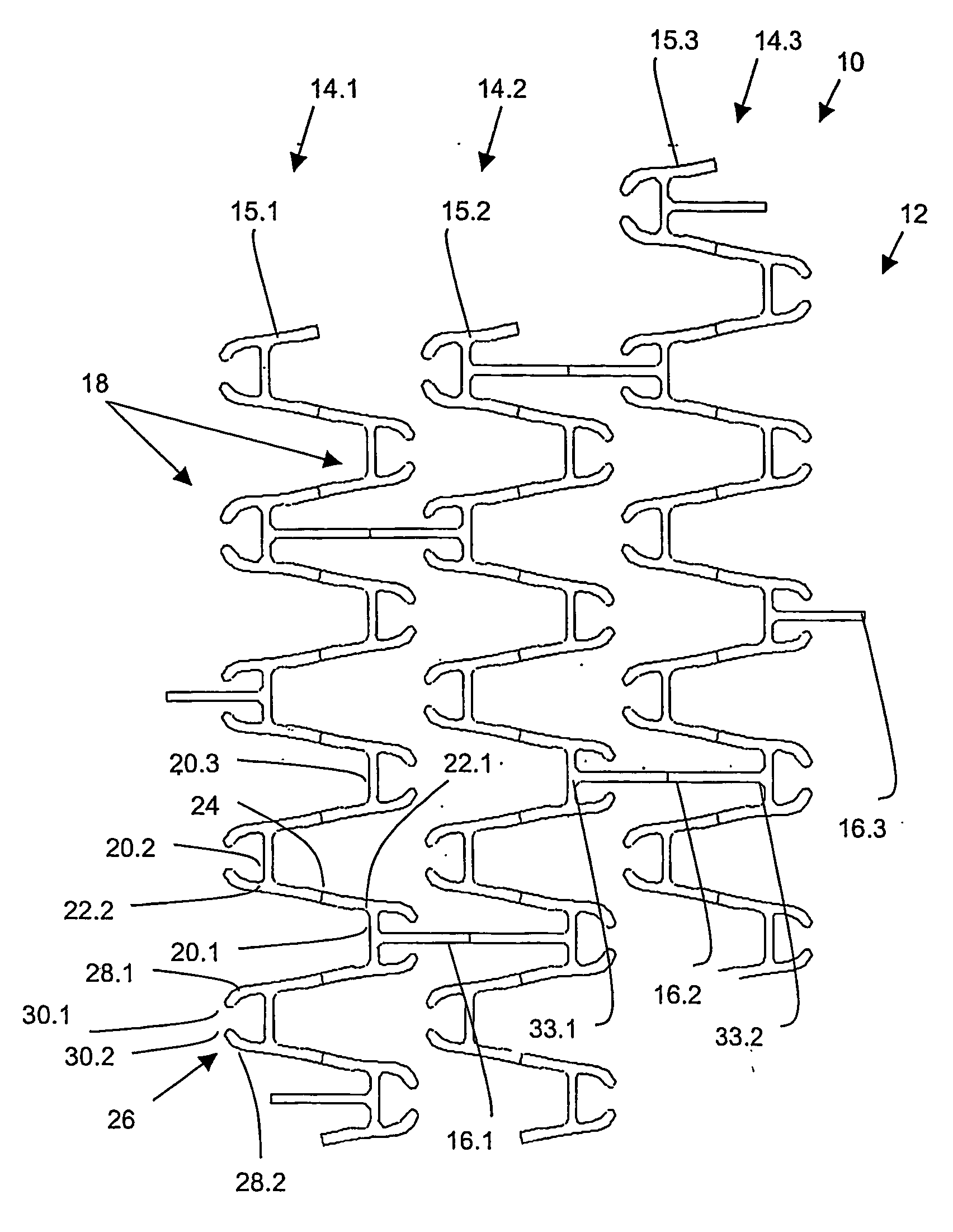
[0040]FIG. 1 diagrammatically shows a section view of a stent 10, namely in a top view of the windings of its tubular circumferential wall 12. A base body of the stent 10 is composed entirely or in part of a multitude of structural segments 14.1, 14.2, 14.3. The individual structural segments 14.1, 14.2, 14.3 are interconnected by way of transverse connectors 16.1, 16.2, 16.3 aligned in longitudinal direction of the stent 10. The design of the transverse connectors 16.1, 16.2, 16.3 is shown only by way of an example.

[0041] In order to enhance the bending flexibility, variants with S-, V-, W- or some other multisinusoidal shape can also be used.

[0042] The structural segments 14.1, 14.2 and 14.3 of FIG. 1 comprise a zigzagging or undulating structure made from a brace 15.1, 15.2, 15.3 that extends circumferentially along the longitudinal axis of the stent 10. As shown in the illustration, in a turning region 18 of the zigzagging or undulating structure, i.e. in the peaks of the indi...

embodiment 2

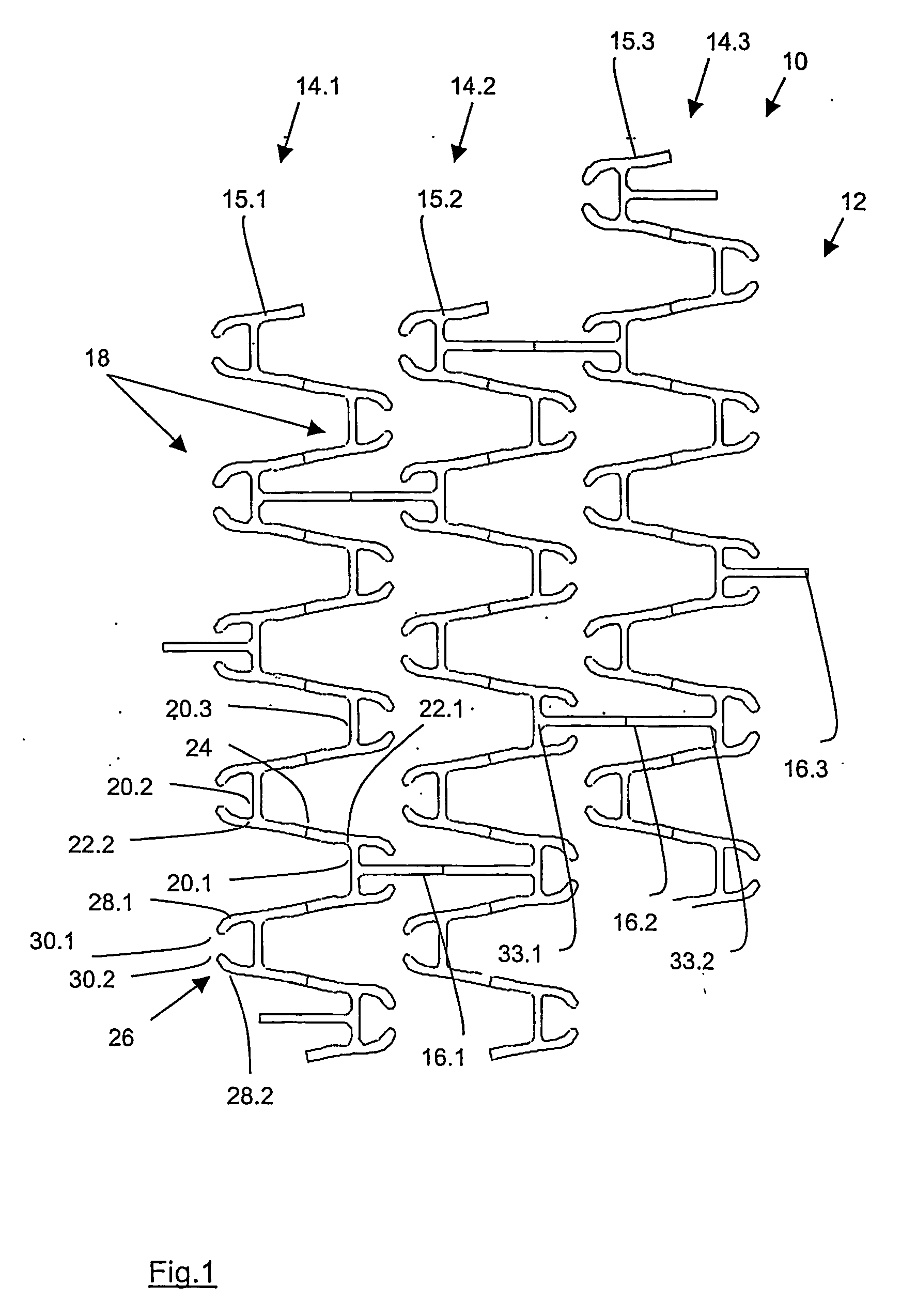
[0045]FIG. 2 diagrammatically shows a section view of a further stent 9 with a multitude of structural segments 11.1, 11.2, 11.3 arranged side by side. The structural segments 11.1, 11.2, 11.3 have a loop structure comprising a brace 13.1, 13.2, 13.3 which circumferentially extends along the longitudinal axis of the stent 9. By way of transverse connectors 17.1, 17.2 the individual structural segments 11.1, 11.2, 11.3 are interconnected in longitudinal extension of the stent 9. The illustration is a top view of the windings of the circumferential wall formed by the individual support segments 11.1, 11.2, 11.3.

[0046] As far as the design options and joining options of the transverse connectors 17.1, 17.2 are concerned, reference is made to the shapes mentioned in embodiment 1.

[0047] In the turning region 19 of the loop structure, i.e. at the tips of the individual loops, the braces 13.1, 13.2. 13.3 comprise straight bending sections 21.1, 21.2, aligned in circumferential direction....

embodiment 3

[0048]FIGS. 3a to 3c provide a three-dimensional view in enlarged sections of a stent 9.1 with a design that is almost identical to that of embodiment 2. The only difference is that in embodiment 3 transverse connectors 17.3, 17.4 now start at each turning region 19.1. The three-dimensional representation of FIG. 3a shows the stent design in the non-expanded state. As can be seen from the enlarged section of FIG. 3b, the two bending sections 21.3, 21.4 in the turning region 19.1 are not aligned exactly in circumferential direction of the stent 9.1, but instead deviate slightly, namely by approximately 8°. FIG. 3c shows an enlarged view of the turning region 19.1 with the two bending sections 21.3, 21.4 and in addition, by means of the dashed line, indicates the deformation of this region during expansion of the stent 9.1.


PUM

PropertyMeasurementUnit
elongation ataaaaaaaaaa
elongationaaaaaaaaaa

Abstract

The invention relates to stents made of a material with an elongation at rupture of 30% or less and with a tubular base body which entirely or in parts comprises structural segments which are interconnected in longitudinal direction of the stents by means of transverse connectors and in which the structural segments comprise a zigzagging or undulating structure of a brace which is wrapped around the longitudinal axis of the stent. Due to the mechanical properties of the materials used, adaptation of the stent design is required. This is achieved in that in a turning region of the zigzagging or undulating structure the brace comprises a straight bending section aligned in circumferential direction.

Description

BACKGROUND OF THE INVENTION [0001] The invention relates to stents made of a material with an elongation at rupture of 30% or less and with a tubular base body which entirely or in parts comprises structural segments which are interconnected in the logitudinal direction of the stents by means of transverse connectors and in which stents the structural segments comprise a zigzagging or undulating structure of a brace which is wrapped around the longitudinal axis of the stent. [0002] Coronary heart disease, in particular acute myocardial infarction, is one of the most frequent causes of death in Western Europe and North America. In more than 80% of cases, myocardial infarction is caused by thrombotic obstruction of a coronary artery as a result of rupture of atheromatous plaque in pre-existing stenosing atheromatosis. The following are decisive factors in the long-term prognosis after acute myocardial infarction: [0003] an effective and long-lasting reopening of the infarction artery;...

Claims


Application Information

Patent Timeline
Patent Type & Authority Applications(United States)
IPC IPC(8): A61F2/90A61F2/02A61F2/91A61F2/915A61L31/14
CPCA61F2/91A61F2/915A61F2002/91533A61F2230/0013A61F2210/0004A61L31/14A61L31/148A61F2002/91575
Inventor LOOTZ, DANIELKOOP, KARSTENBAKCZEWITZ, FRANKKIEKBUSCH, MARTINBECHER, BAERBEL
Owner BIOTRONIK AG
Why Eureka
Try Eureka