Method for measuring shear load of fastening tool

a technology of fastening tool and shear load, which is applied in the direction of measuring torque/twisting force while tightening, fastening means, screws, etc., can solve the problems of difficult to verify the accuracy of analysis results made using finite element methods, difficult to rigorously predict the actual load of each bolt in a bolted joint, etc., to achieve high precision, exceptionally reproducible, and easy improvement of measurement sensitivity

Inactive Publication Date: 2007-06-28
HONDA PATENTS & TECH NORTH AMERICA
View PDF15 Cites 28 Cited by
  • Summary
  • Abstract
  • Description
  • Claims
  • Application Information

AI Technical Summary

Benefits of technology

[0020] According to the above shear load measuring method of the present invention, even in structures wherein a plurality of members are fastened with numerous fastening tools for purposes of redundancy, the shear load acting on individual fastening tools can be accurately measured, considerably higher levels of structural design can be attained, and attributes such as the reliability and weight of the structures can be improved.
[0022] Since the optical fiber sensor is disposed in a shallow (0.3 mm) channel on an outer surface of the fastening tool, high precision may be expected, while the positioning operation is straightforward and exceptionally reproducible. The measurement sensitivity is also readily improved. In addition, the fact that the channel is shallow means that the shaft diameter of the fastening tool is substantially unaffected and no correction needs to be made for the channel, allowing shear load to be obtained with high precision.
[0023] The measurement sensitivity can be maintained even if the thickness of the fastened members varies, irrespective of where the shear plane is located on the fastening tool. According to the present invention, furthermore, shear load results can be obtained with a single measuring instrument irrespective of the thickness of the fastened members. Therefore, the measuring tool offers an exceptionally broad range of application, and large reductions in the cost of the measuring tool may be expected.

Problems solved by technology

Bolts used in such bolted joints are subjected to loads and shear forces from the parts used to form the holes into which the bolts are inserted.
Rigorous predictions of the actual load on each bolt in a bolted joint are therefore difficult to make merely by using finite element method (FEM) analysis, which is usually used for stress analysis.
It is also difficult to verify the accuracy of the results of analysis made using the finite element method.
The analytically optimal design of bolted joints, which transmit large loads in aircraft and the like, has thus been difficult.
So far, however, no precise method has yet emerged for directly measuring bolt load distribution; the only method has involved indirectly measuring the load distribution of the bolts by attaching strain gauges to the perimeter of the bolt holes and measuring strain at those locations.
Fixing the optical fiber sensor in this manner has been extremely difficult.

Method used


Image

  • Method for measuring shear load of fastening tool
  • Method for measuring shear load of fastening tool
  • Method for measuring shear load of fastening tool

Examples


first embodiment

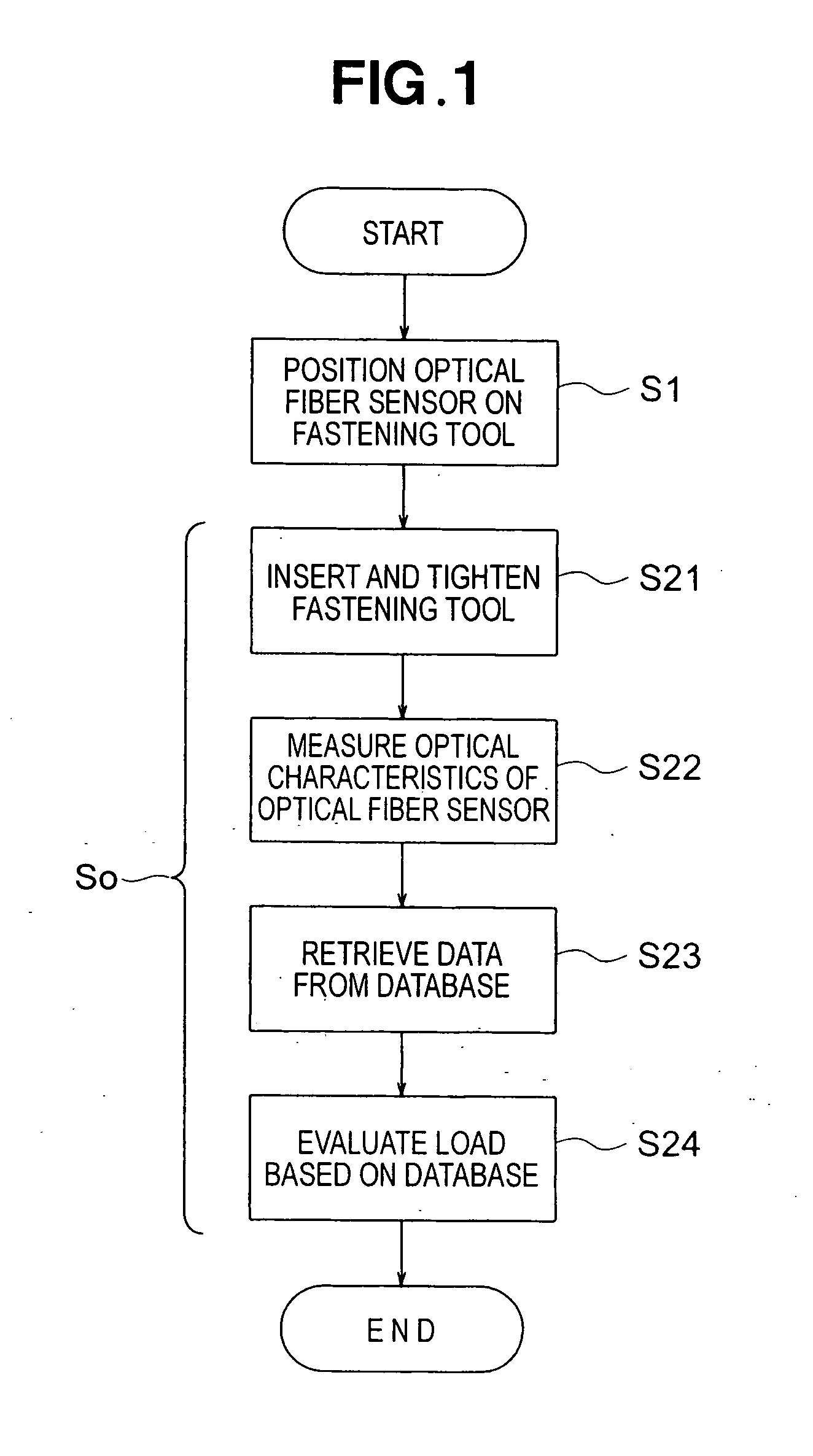
[0046] Initial reference is made to the flow chart of FIG. 1 showing a method for measuring shear load on a fastening tool, according to the present invention.

[0047] The method for measuring shear load on a fastening tool comprises: a sensor-positioning step S1 for positioning an optical fiber sensor on a surface of a fastening tool to be subjected to a measurement, or within the tool but near the surface (at a location proximal to the surface) thereof, so that the optical fiber sensor is positioned along a direction of an axis (longitudinal direction) of the fastening tool; and a measuring step S2 for measuring shear load acting on the fastening tool, based on a change in an optical characteristic of the optical fiber sensor that directly corresponds to a deformation of the fastening tool when shear load is applied to the fastening tool.

[0048] The measuring step S2 further comprises: a step S21 for inserting and tightening the fastening tool; a step S22 for measuring the optical c...

second embodiment

[0097]FIG. 19 is a basic structural diagram of the measurement system used in a method for measuring shear load on a fastening tool, according to the present invention. Of the optical fiber sensors 34 through 45 that are provided to the plurality of bolts 22 through 33 shown in FIGS. 5 and 6, the optical fiber sensors that are provided to bolts for which shear load is to be measured are connected to the light source 51 on one end and are connected to the optical detection part 52 on the other end. The measurement of the shear load on the bolt 22 will be described in this example.

[0098] Since the light source 51 and the optical detection part 52 are the same as in the first embodiment, the same notation will be used and a description will be omitted.

[0099] The optical fiber sensor 34 has a sensor part 34s, introduces light (incident light L1) from the light source 51 into the sensor part 34s, and detects light L3 transmitted from the sensor part 34s.

[0100] The optical detection par...


PUM


Abstract

A method for measuring shear load of a fastening tool, which comprises the steps of: positioning an optical fiber sensor on a surface of a fastening tool to be subjected to a measurement, or within the tool but near the surface thereof, so that the optical fiber sensor is positioned along a direction of an axis the fastening tool; and measuring the shear load acting on the fastening tool on the basis of a change in an optical characteristic of the optical fiber sensor that directly corresponds to a deformation of the fastening tool when the shear load is applied to the fastening tool.

Description

FIELD OF THE INVENTION [0001] The present invention relates to a method for measuring shear load of a fastening tool and particularly relates to a method for measuring shear load of a fastening tool that uses an optical fiber sensor. BACKGROUND OF THE INVENTION [0002] Bolted joints in aircraft transmit large loads and are usually fastened using a plurality of bolts in order to lower the surface pressure between members and increase redundancy. Bolts used in such bolted joints are subjected to loads and shear forces from the parts used to form the holes into which the bolts are inserted. The actual load (load distribution) on each of the bolts of a bolted joint in such instances varies in accordance with the deformation of each bolt and hole. Rigorous predictions of the actual load on each bolt in a bolted joint are therefore difficult to make merely by using finite element method (FEM) analysis, which is usually used for stress analysis. It is also difficult to verify the accuracy o...

Claims


Application Information

Patent Timeline
Patent Type & Authority Applications(United States)
IPC IPC(8): F16B31/02
CPCG01L5/24
Inventor SATO, KEIICHIMURAYAMA, HIDEAKIKAGEYAMA, KAZURO
Owner HONDA PATENTS & TECH NORTH AMERICA
Why Eureka
Try Eureka