Fuel cutoff valve

a technology of fuel cutoff valve and valve body, which is applied in the direction of mechanical equipment, functional valve types, transportation and packaging, etc., can solve the problems of restoring the upper portion of the valve body to the horizontal force, the sealing ability declines, etc., and achieves stable horizontal attitude, high sealing ability, and stable attitude.

Active Publication Date: 2007-06-28
TOYODA GOSEI CO LTD
View PDF4 Cites 3 Cited by
  • Summary
  • Abstract
  • Description
  • Claims
  • Application Information

AI Technical Summary

Benefits of technology

[0038] The design of the embodiment discussed above affords the following effects and advantages.
[0039] (4)-1 Once the fuel level in the fuel tank produced by fueling reaches the prescribed level FL1 at which the guide opening 39b becomes blocked, the tank internal pressure within the fuel tank FT will rise, causing the auto stop function to operate.
[0040] (4)-2 Since the valve mechanism 60 is supported at the supported part 66b at a single point of support by means of the supporting face 56a of the supporting portion 55a provided on the upper part of the float 52, and moreover the center of gravity of the valve mechanism 60 is at a location below the point of support, the valve mechanism 60 will be balanced about the point of support and will have a stable attitude. Furthermore, since the supporting face 56a is a flat surface while the supported portion is a convex portion, even if the convex portion should experience a certain amount of wear, the function of maintaining a horizontal attitude will not suffer. Consequently, even if the float 52 should tilt due to leaning of the automobile, the valve mechanism 60 can be maintained in a stable horizontal attitude for an extended period, affording reliable contact with and release from the seal portion 31c of the connecting passage 31b, and high sealing ability.
[0041] (4)-3 Since the valve mechanism 60 per se operates in such a way as to stabilize attitude on the same basic principle as a balance toy, the force pressing on the seal portion 31c will be low, and the lifting force required of the float 52 in to open the valve will be low as well, so it is possible to respond to slight rises in fuel level produced during leaning of the automobile for example. Moreover, despite the fact that the supported part 66b constituted by the convex shape of the valve mechanism 60 is supported by the supporting face 56a at a location different from the centerline of the float 52, the attitude of the valve mechanism 60 will be stable since it is balanced with the supported part 66b as the point of support.
[0042] (4)-4 In association with the rising level of fuel within the fuel tank during fueling, fuel vapors that have collected in the upper space of the fuel tank FT form a rising current within the valve chamber 30S and enter into the support hole 62c of the first valve unit 61, but then pass through the gap between the support hole 62c and the guide cylinder 66f to escape from the vent hole 62e. For this reason, the rising current flowing through the support hole 62c does not collect in the upper portion of the support hole 62c, but instead escapes through the vent hole 62e. Consequently, there is no localized rise in pressure within the support hole 62c that would cause force pulling the second valve unit 65 apart from the first valve unit 61 to be exerted. Moreover, the guide portion 62f of the first valve unit 61 is formed on the inside wall of the support hole 62c, and the second valve unit 65 is guided with respect to the first valve unit 61, without tilting. Consequently, the second valve unit 65 will not experience tilting during its ascent, and the second seal portion 66c will become seated in the seat portion 64c with a high degree of sealing ability, thus avoiding the problems associated with loss of sealing ability between these parts, specifically, problems such as fuel flowing to the outside through the connecting hole 64b and the connecting passage 31b.
[0043] (4)-5 The spring 68 interposed between the valve mechanism 60 and the float 52 applies force in the opening direction of the valve mechanism 60 even with the valve mechanism 60 in the submersed state, so that even if the fuel cutoff valve 10 should be subjected to slight vibration caused by vibration of the vehicle for example, the seat portion 64a of the valve mechanism 60 will not readily release from the seal portion 31c, and the vibration will not act to the extent that opening of the valve mechanism 60 occurs.

Problems solved by technology

However, the upper portion valve body is susceptible to being supported by the projection of the float in an attitude of displacement away from the center of the upper portion valve body.
A resultant problem is that the attitude of the upper portion valve body is not stable, so that sealing ability declines due one-sided contact with the seal portion of the connecting passage.
However, a problem with the fuel cutoff valve is that a projection of the upper portion valve body is point-bearing and has a conical shape in order to stabilize the attitude, and when the distal end thereof becomes worn with service for an extended period, there is a drop in the force restoring the upper portion valve body to the horizontal position.

Method used


Image

  • Fuel cutoff valve
  • Fuel cutoff valve
  • Fuel cutoff valve

Examples


Embodiment Construction

(1) Simple Arrangement of Fuel Cutoff Valve 10

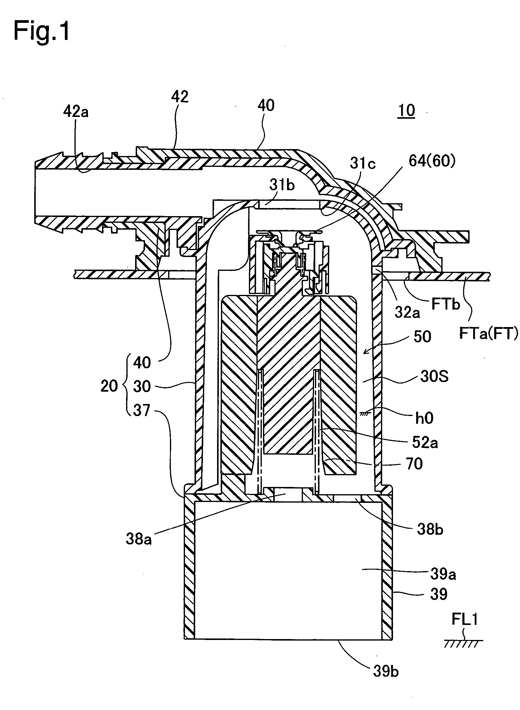
[0023]FIG. 1 is a sectional view depicting a fuel cutoff valve 10 pertaining to an embodiment of the invention, shown attached to the upper portion of an automobile fuel tank FT. In FIG. 1, the fuel tank FT is formed from composite synthetic resin that includes polyethylene on its surface; a mounting hole FTb is formed in the tank upper wall FTa. The fuel cutoff valve 10 is attached with the lower portion thereof being inserted into the mounting hole FTb. The fuel cutoff valve 10 functions to restrict outflow from the canister once the fuel level within the tank has reached a prescribed level during fueling.

(2) Arrangement of Parts of Fuel Cutoff Valve 10

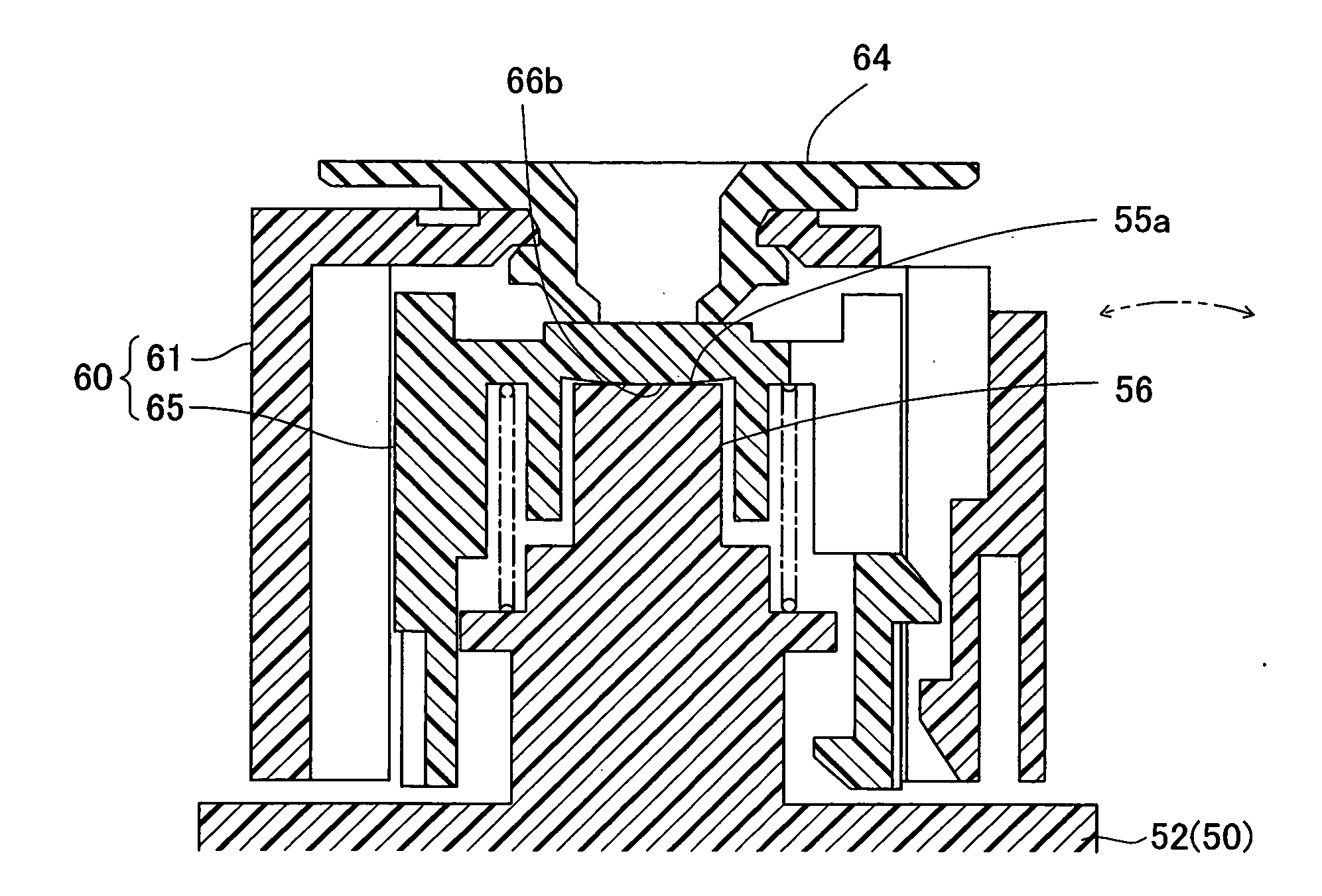
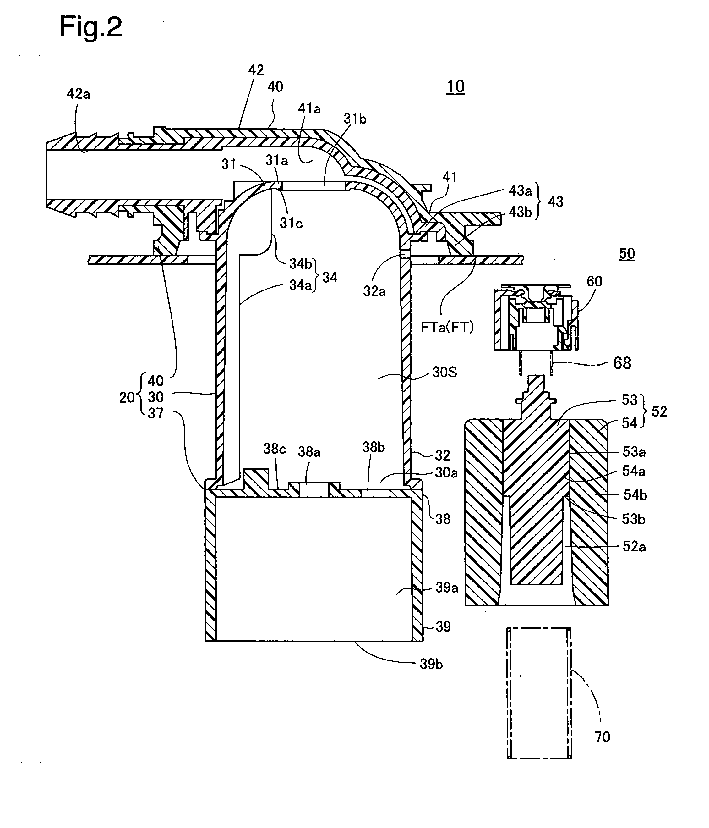
[0024] The fuel cutoff valve 10 comprises mainly a casing 20, a float mechanism 50, and a spring 70. The casing 20 comprises a casing body 30, a base member 37, and a cover 40. The space enclosed by the casing body 30 and the base member 37 constitutes a valve chamber 30S, and the float...


PUM


Abstract

The fuel cutoff valve comprises a float and a valve mechanism situated within the valve chamber of a casing. The float has a supporting portion disposed in the upper portion of the float for supporting the valve mechanism, and having a supporting face formed with a flat surface or concave surface. The valve mechanism comprises a comprises a first valve main body having a supported part of convex shape supported on the supporting face, and a seat portion disposed on the first valve main body for opening and closing a connecting passage. The center of gravity of the valve mechanism is established below the point of support, when the supported part is supported on the supporting face so as to be balanced with the supported lower end portion as the point of support.

Description

[0001] This application claims the benefit of and priority from Japanese Application No. 2005-377646 filed Dec. 28, 2005, the content of which is incorporated herein by reference. BACKGROUND OF THE INVENTION [0002] 1. Field of the Invention [0003] The present invention relates to a fuel cutoff valve installed on the upper portion of a fuel tank for the purpose of shutting off communication of the fuel tank with the outside by means of opening or closing of a connecting passage that connects the fuel tank interior with the outside. [0004] 2. Description of the Related Art [0005] A fuel cutoff valve is disclosed in JP-A 7-279789. Specifically, the fuel cutoff valve is mounted on the upper portion of a fuel tank, and comprises a casing having in the upper portion thereof a connecting passage for connection to the outside (a canister), a float for increasing or decreasing buoyancy and rising or falling according to the fuel level within the valve chamber, and an upper portion valve body...

Claims


Application Information

Patent Timeline
Patent Type & Authority Applications(United States)
IPC IPC(8): F16K24/04
CPCF16K24/044Y10T137/3099
Inventor KANEKO, KENICHIRO
Owner TOYODA GOSEI CO LTD
Why Eureka
Try Eureka