Representation of whirl in fixed cutter drill bits

a technology of fixed cutter and drill bit, which is applied in the direction of cad techniques, instruments, manufacturing tools, etc., can solve the problems that the bit may not be suitable for drilling a borehole, and achieve the effect of improving the selection of the bi

Active Publication Date: 2007-06-28
REEDHYCALOG UK
View PDF99 Cites 31 Cited by
  • Summary
  • Abstract
  • Description
  • Claims
  • Application Information

AI Technical Summary

Benefits of technology

[0014] This invention is also a method of comparing the relative lateral stability among drill bits (that is, the tendency for a bit to whirl). This allows improved bit selection in applications where whirl is apparent. Because there will likely be many different acceptable bit designs produced by the above method, the comparison of the regenerative forces among these bits allows a customer to make a more informed choice between stability and other performance features among a range of bit designs.

Problems solved by technology

In making these selections, designers must also consider other aspects of the bit design such as durability, aggressivity and steerability, else the resulting bit may not be suitable for drilling a borehole.

Method used


Image

  • Representation of whirl in fixed cutter drill bits
  • Representation of whirl in fixed cutter drill bits
  • Representation of whirl in fixed cutter drill bits

Examples


Embodiment Construction

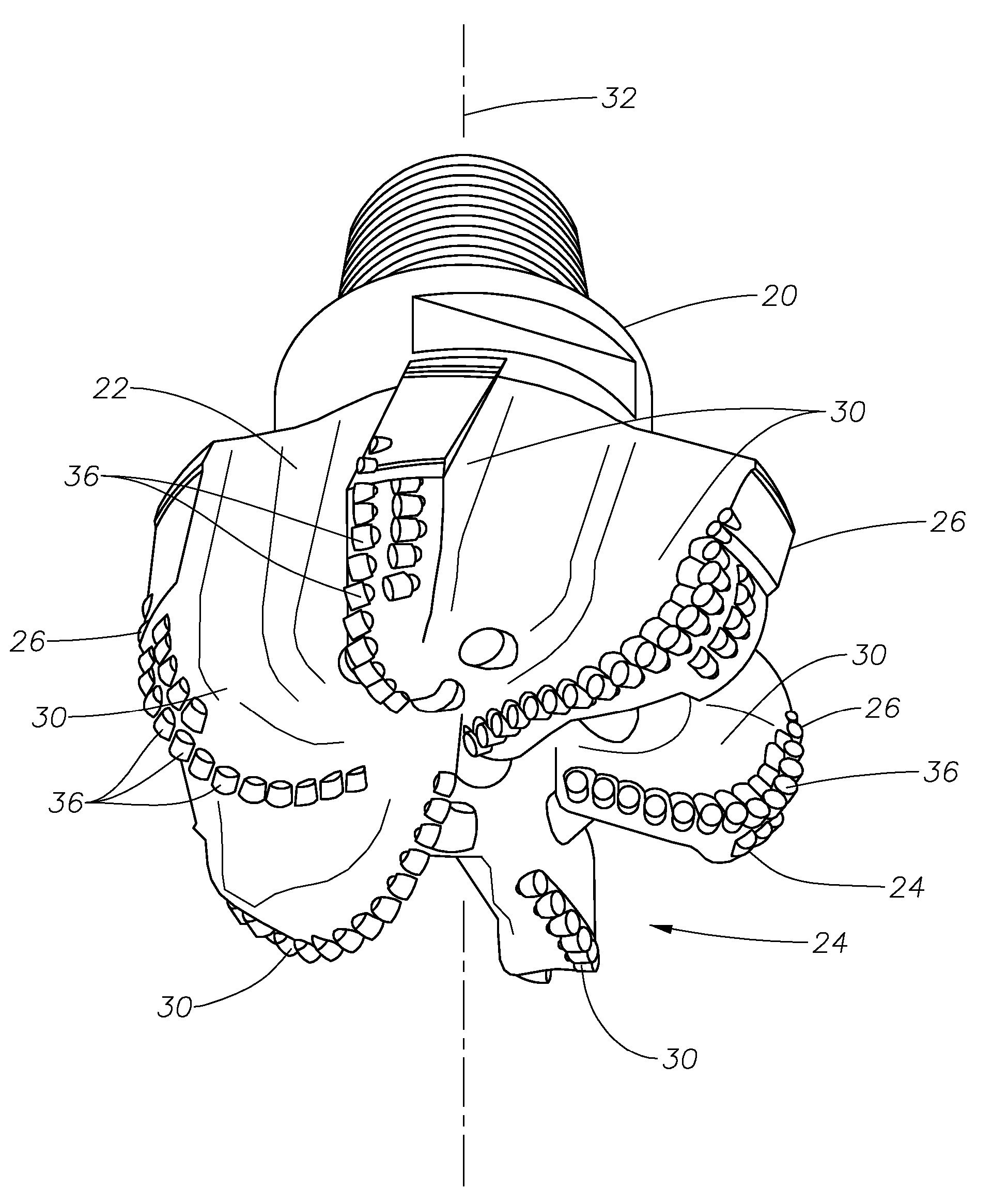
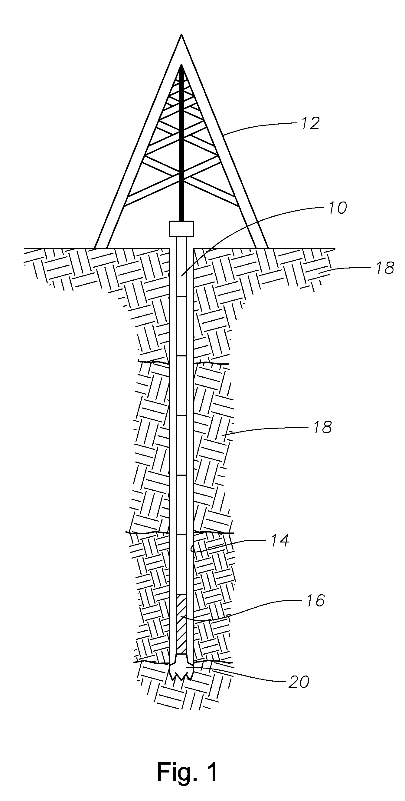
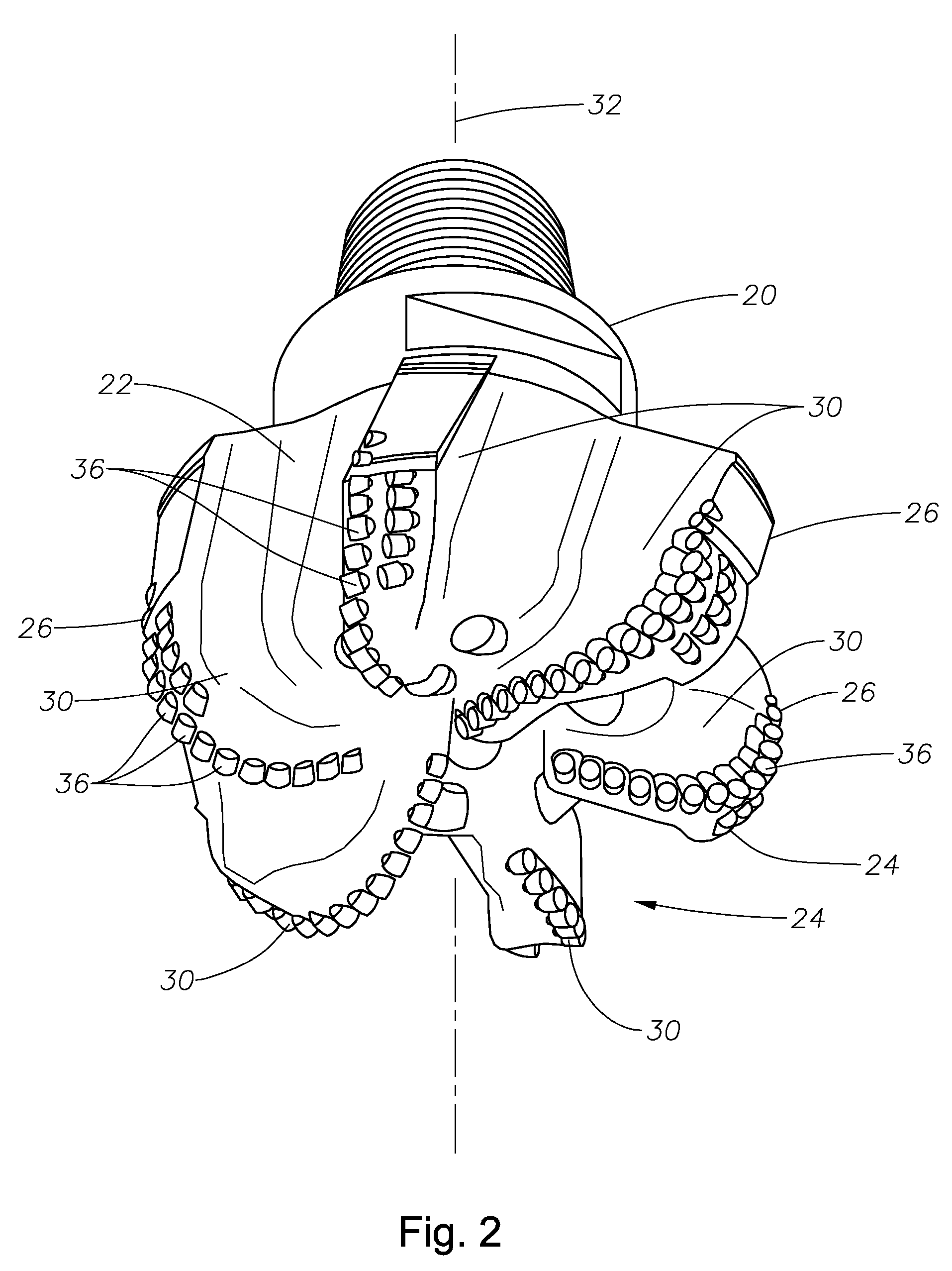
[0021]FIG. 1 shows a drill string 10 suspended by a derrick 12 for drilling a borehole 14 into the earth 18 for minerals exploration and recovery, particularly petroleum and natural gas. A bottom-hole assembly (BHA) 16 is located in the drill string 10 at the bottom of the borehole 14. The BHA 16 includes a fixed cutter drill bit 20 (shown in more detail in FIGS. 2 and 3) having a bit body 22, a leading face 24, and a gauge region 26. The drill bit 20 is caused to rotate downhole as it penetrates into the earth allowing the drill string 10 to advance, forming the borehole 14.

[0022] The fixed cutter drill bit 20 is designed with predictable stability, that is, the bit is designed such that its tendency to ‘whirl’ is predicted in advance so that its properties in operation can be matched to the drilling requirements. Although it is generally believed that the less ‘whirl’ a bit has, the better, there are circumstances where there is a trade off between ‘whirl’ tendency and drilling r...


PUM


Abstract

Disclosed is a method of comparing the relative lateral stability among drill bits (that is, the tendency for a bit to whirl). This allows improved bit selection in applications where whirl is apparent. Because there will likely be many different acceptable bit designs produced by the above method, the comparison of the regenerative forces among these bits allows a customer to make a more informed choice between stability and other performance features among a range of bit designs.

Description

BACKGROUND OF THE INVENTION [0001] 1. Field of the Invention [0002] The invention relates to fixed cutter drill bits for drilling boreholes into the earth for the exploration and recovery of minerals, particularly petroleum and natural gas. [0003] 2. Description of the Related Art [0004] Bit whirl has been documented as a major cause of early failure and reduced performance of PDC bits. To date numerous methods have been developed with the aim of eliminating bit whirl. These methods include summing the resultant forces from each PDC cutter on a drill bit and balancing them to give a low net resultant force, known as an Out of Balance force. This was further developed by Warren et al in two related publications (“Bit Whirl, a New Theory of PDC bit Failure”—J. Ford Brett, Thomas F. Warren, and Suzanne M. Behr; Society of Petroleum Engineers (SPE) Paper No. 19571) and (“Development of a Whirl Resistant Bit”—Thomas M. Warren, J. Ford Brett and L. Allen Sinor; SPE Paper No. 19572) such t...

Claims


Application Information

Patent Timeline
Patent Type & Authority Applications(United States)
IPC IPC(8): E21B10/36E21B10/43G06F17/50
CPCE21B10/43G06F17/50G06F2217/16G06F2111/10G06F30/00E21B10/42G06F30/17
Inventor JOHNSON, SIMONJARVIS, BRIAN PETER
Owner REEDHYCALOG UK
Why Eureka
Try Eureka