
Pixel and CMOS image sensor including the same

a technology of cmos and image sensors, applied in semiconductor devices, television systems, radio control devices, etc., can solve the problems of ccd image sensors that may operate, ccd image sensors may consume more power than cmos image sensors, and may drive ccd image sensors, etc., to achieve the effect of increasing conversion gain

Inactive Publication Date: 2007-06-28
SAMSUNG ELECTRONICS CO LTD
View PDF3 Cites 14 Cited by
  • Summary
  • Abstract
  • Description
  • Claims
  • Application Information

AI Technical Summary

Benefits of technology

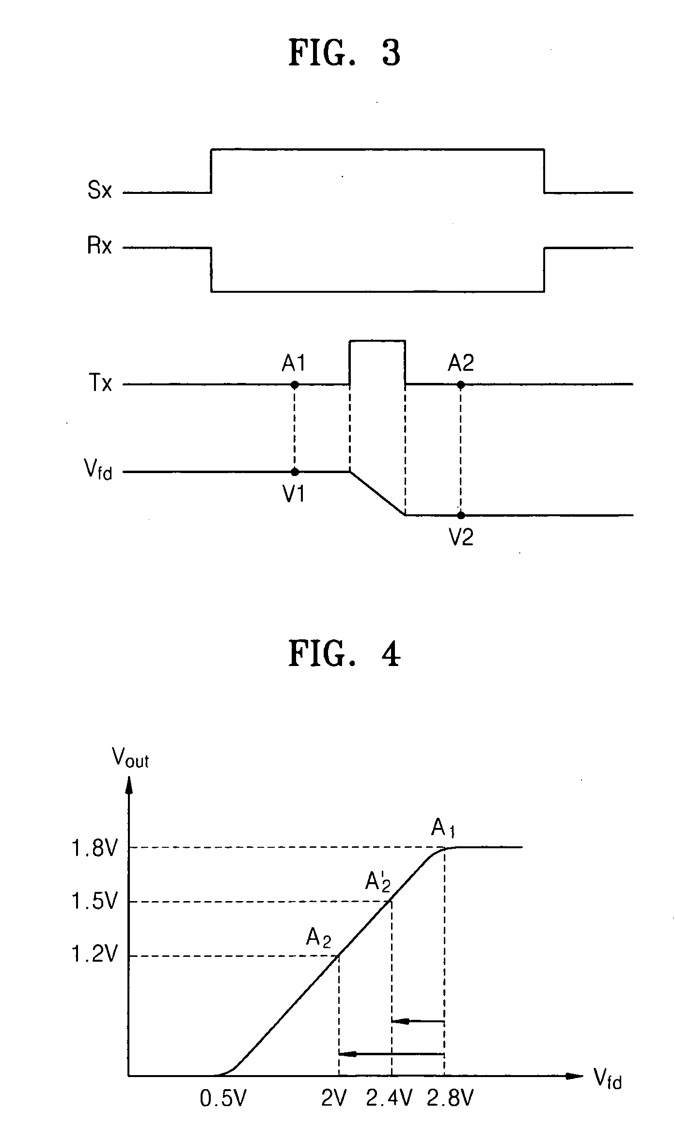
[0016] Example embodiments may provide a pixel and / or a complementary metal-oxide semiconductor (CMOS) image sensor including the pixel which may address the problem of backflow of photocarriers caused due to an increase in conversion gain. Example embodiments may provide a method of operating the pixel.
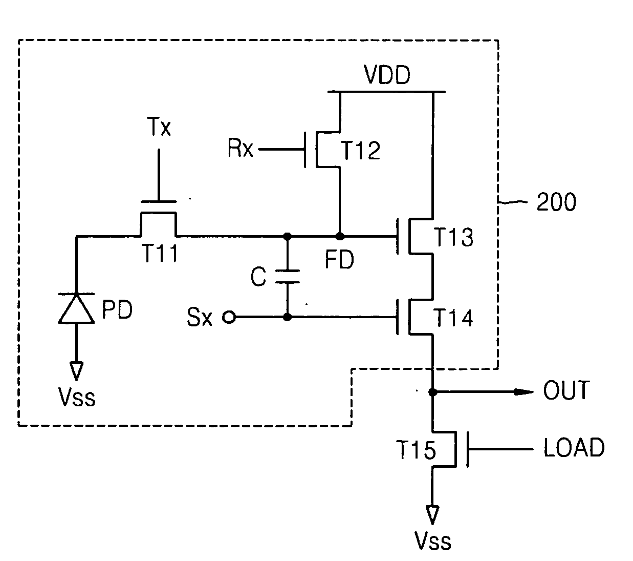
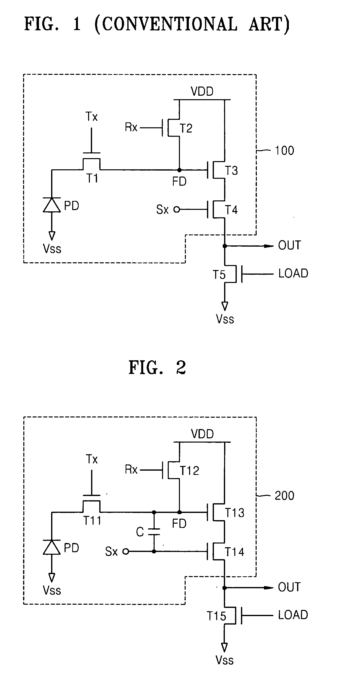
[0024] According to an example embodiment, a pixel may include a photodiode which may convert light energy into photocarriers, a transfer transistor which may transfer the photocarriers accumulated in the photodiode to a floating diffusion region, a select transistor which may transmit a data signal externally in response to a selection control signal, the externally transmitted data signal having a voltage which varies according to the voltage of the floating diffusion region, and / or at least one capacitor which may be connected in parallel to a capacitance component of the floating diffusion region and which may increase the equivalent capacitance of the floating diffusion region.

Problems solved by technology

Driving CCD image sensors, which may operate in the aforementioned manner, may be more complicated than driving CMOS image sensors, and CCD image sensors may consume more power than CMOS image sensors.
However, there may still be a clear limit in increasing the effective area of the photodiode PD as the integration density of electronic devices may increase.
Conventional CMOS image sensors may not, however, address the problem of an increasing conversion gain value.

Method used


Image

  • Pixel and CMOS image sensor including the same
  • Pixel and CMOS image sensor including the same
  • Pixel and CMOS image sensor including the same

Examples


Embodiment Construction

[0032] Example embodiments will now be described more fully with reference to the accompanying drawings. Embodiments may, however, be in many different forms and should not be construed as being limited to the example embodiments set forth herein. Rather, these example embodiments are provided so that this disclosure will be thorough and complete, and will fully convey the scope to those skilled in the art. In the drawings, the thicknesses of layers and regions may be exaggerated for clarity.

[0033] It will be understood that when a component is referred to as being “on,”“connected to” or “coupled to” another component, it can be directly on, connected to or coupled to the other component or intervening components may be present. In contrast, when a component is referred to as being “directly on,”“directly connected to” or “directly coupled to” another component, there are no intervening components present. As used herein, the term “and / or” includes any and all combinations of one o...


PUM


Abstract

A pixel which may prevent the voltage of a floating diffusion region of the pixel from being outside a desired or predetermined driving voltage range by adjusting the equivalent capacitance of the floating diffusion region may be provided. The pixel may include a photodiode which may convert light energy into photocarriers, a transfer transistor which may transfer the photocarriers accumulated in the photodiode to a floating diffusion region, a select transistor which may transmit a data signal to the exterior in response to a selection control signal, the transmitted data signal having a voltage which may vary according to the voltage of the floating diffusion region, and / or at least one capacitor which may be connected between the floating diffusion region and the select transistor and which may adjust the equivalent capacitance of the floating diffusion region.

Description

PRIORITY STATEMENT [0001] This application claims the benefit of priority to Korean Patent Application No. 10-2005-0131888, filed on Dec. 28, 2005, in the Korean Intellectual Property Office, the entire contents of which is incorporated herein in its entirety by reference. BACKGROUND [0002] 1. Field [0003] Example embodiments relate to a pixel and / or a complementary metal-oxide semiconductor (CMOS) image sensor including the pixel, and for example, to a pixel and / or CMOS image sensor including the pixel which may adjust the equivalent capacitance of a floating diffusion region by disposing a capacitor between the floating diffusion region and / or may select a transmitter. Example embodiments relate to a method of operating the pixel and / or a CMOS image sensor including the pixel. [0004] 2. Description of Related Art [0005] Image sensors may be classified into charge coupled device (CCD) image sensors or complementary metal-oxide semiconductor (CMOS) image sensors. CCD image sensors m...

Claims


Application Information

Patent Timeline
IPC IPC(8): H01L31/113
CPCH04N5/3559H04N5/37452H04N25/59H04N25/771H01L27/146
Inventor LEE, YONGAHN, JUNG-CHAKKO, JU-HYUNHWANG, SUNG-IN
Owner SAMSUNG ELECTRONICS CO LTD
Learn More