Analyzing radiological image using 3D stereo pairs

Inactive Publication Date: 2007-06-28
CARESTREAM HEALTH INC
View PDF16 Cites 57 Cited by
  • Summary
  • Abstract
  • Description
  • Claims
  • Application Information

AI Technical Summary

Benefits of technology

[0037] This invention provides a way to produce 3D stereo depth perception from stereo pair images of medical images, with significantly reduced the computational load and provide the potential for adapting an aftermarket true stereo viewer to existing systems providing a single sequence of volumetric rendered monocular views (e.g. the ability to view a volumetric

Problems solved by technology

However, these artistic techniques for displaying 3D volumetrically rendered images on a single, unaltered planar 2D display media device can not produce binocular disparity in the human eye-brain system.
Unfortunately, it is not uncommon for many of these 3D stereo devices to induce eye fatigue and/or motion sickness in users.
Although radiologists are trained to visualize the “slice images” in 3D in their mind's eye, other professionals who normally work in 3D (e.g. surgeons, etc.) cannot as easily visualize in 3D.
However, with the ever-increasing res

Method used


Image

  • Analyzing radiological image using 3D stereo pairs
  • Analyzing radiological image using 3D stereo pairs
  • Analyzing radiological image using 3D stereo pairs

Examples


Embodiment Construction

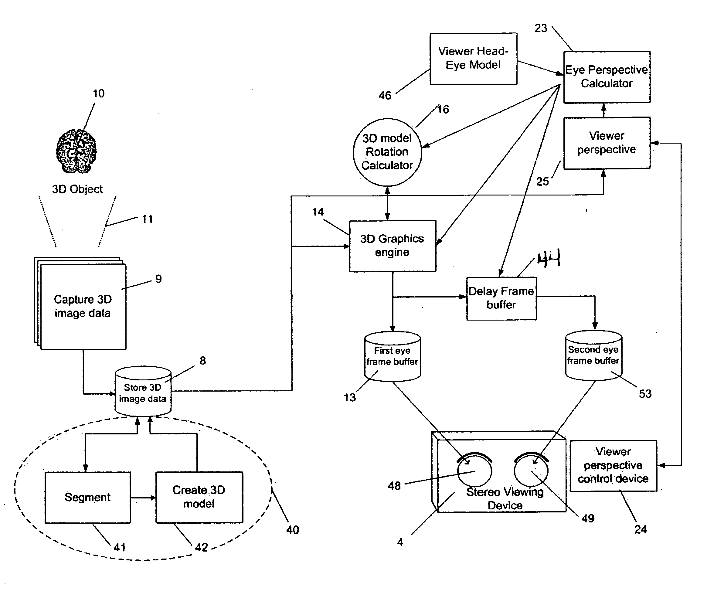
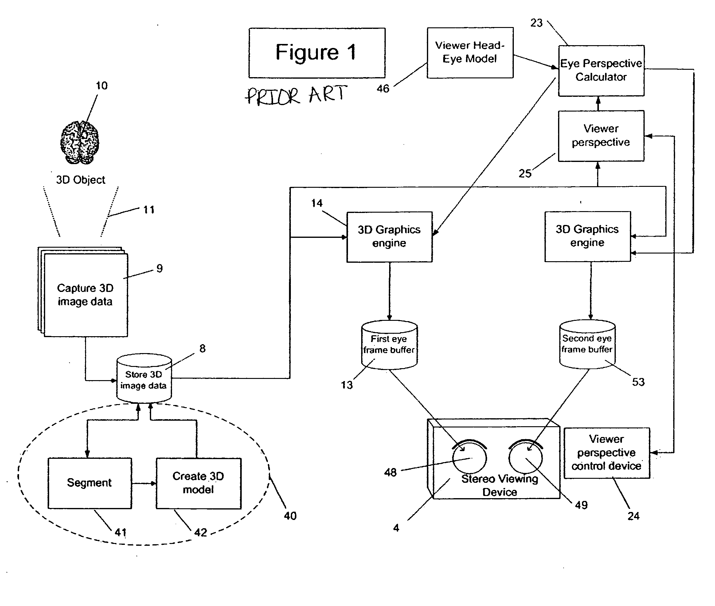
[0048]FIG. 1 is a schematic of a prior art stereo pair calculation from 3D image model using 3D stereo pairs and is shown as background for this invention. Many of these components are also used in FIG. 2 and are explained in the context of the present invention. Of particular distinction is the presence of two (2) 3D graphics engines 14 shown in FIG. 1 as prior art. This invention, as 25 described in FIG. 2, uses a single 3D graphics engine 14 with the addition of the 3D model rotation calculator 16 and delay frame buffer 44 not used in the FIG. 1 prior art.

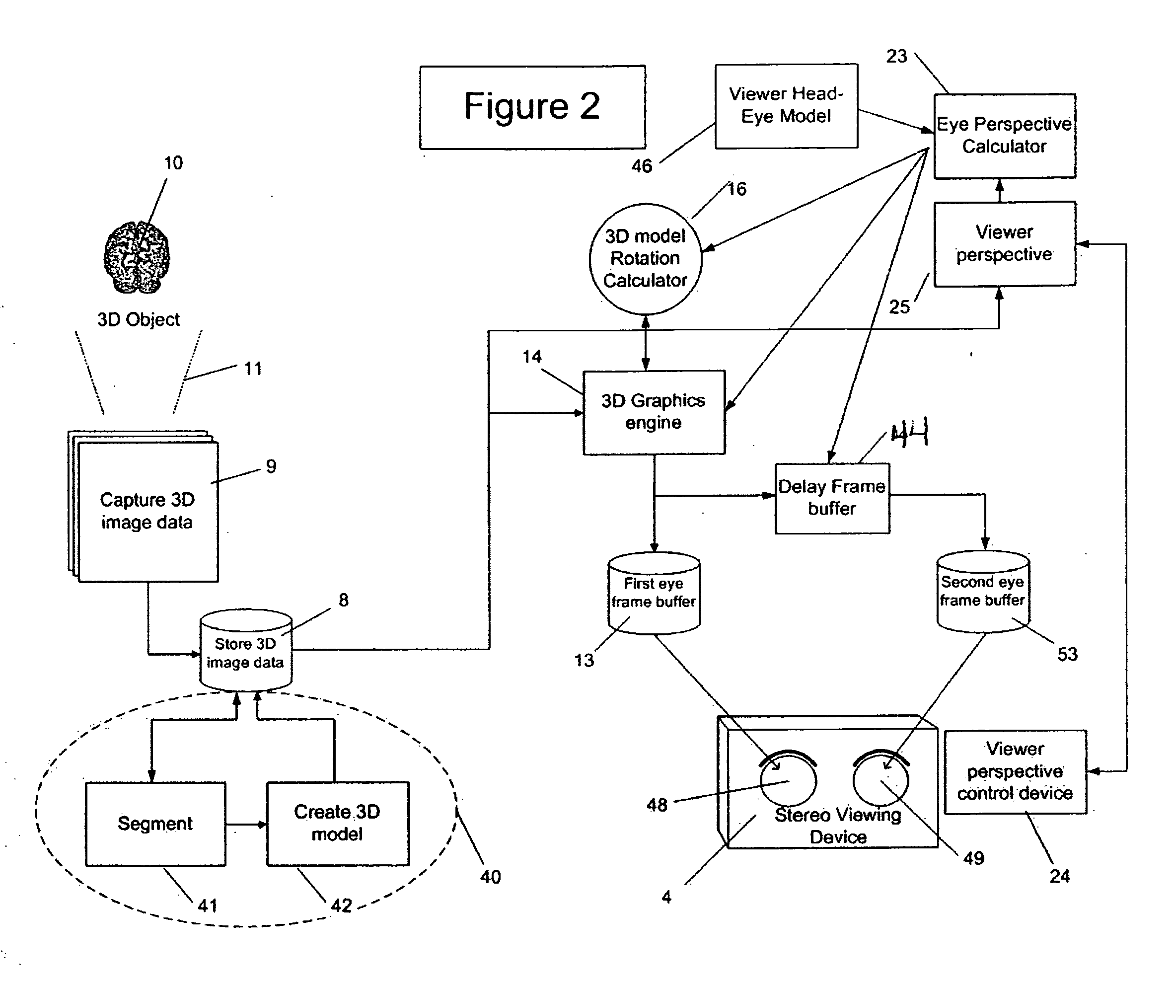
[0049]FIG. 2 shows the system of this invention for analyzing medical images 9 using 3D stereo pairs. Medical image data 9 is captured by scanning object 10 using scanner 11 which is capable of producing 3D image data. This medical image data 9 is stored in data storage 8.

[0050] Image segmentation 41 is performed on the medical image data 9 resulting in labeled regions of medical image data 9 that belong to the same or similar...


PUM


Abstract

A system for analyzing radiological images using three-dimensional (3D) stereo pairs comprises capturing 3D image data; storing the 3D image data; segmenting the 3D image data; creating a model from the segmented 3D image data; creating a first 3D volumetric monocular-view image for the current model position; rotating the model a prescribed amount and creating a second 3D volumetric monocular-view image for the rotated position; creating the 3D stereo pair using the first and second 3D volumetric monocular-view images; and viewing the 3D stereo pair on a 3D stereo viewer.

Description

FIELD OF THE INVENTION [0001] This invention relates in general to medical images and in particular to viewing of three-dimensional (3D) stereo pairs. BACKGROUND OF THE INVENTION [0002] It is desirable to provide medical professionals with a system for viewing true three-dimensional (3D) stereo images captured using 3D radiographic modalities. Examples of medical radiographic modalities commonly used to capture 3D medical images are: CT-scanners, MR-scanners, PET-scanners, and cone-beam CT scanners. [0003] The scanner energy source(s) and imaging detector(s) are located at specific geometric positions with respect to the 3D object to be scanned. The positions depend on the object being scanned, the physics of the energy source and imaging detector, and the structures in the scanned 3D object to be viewed in the images. The scanner captures 3D image data of the object being scanned by taking a time-sequence of images while moving the energy source(s) and imaging detector(s) through a...

Claims


Application Information

Patent Timeline
IPC IPC(8): G06K9/00
CPCG06T2207/10012G06T2210/41H04N13/0011H04N13/0275H04N13/111H04N13/275
Inventor DI VINCENZO, JOSEPH P.SQUILLA, JOHN R.SCHAERTEL, DANIEL P.BLISH, NELSON A.
Owner CARESTREAM HEALTH INC
Why Eureka
Try Eureka