Optical fiber with specialized index profile to compensate for bend-induced distortions

a technology of index profile and optical fiber, applied in the field of large mode area optical fiber, can solve the problems of increasing the presence of other fiber-related sensitivities, need to bend, even spooling such fibers, and restricting the physical ability of the fiber to bend, so as to minimize the effect of the reduction of the effective area of the fiber

Inactive Publication Date: 2007-06-28
OFS FITEL LLC
View PDF27 Cites 74 Cited by
  • Summary
  • Abstract
  • Description
  • Claims
  • Application Information

AI Technical Summary

Benefits of technology

[0007] The need remaining in the prior art is addressed by the present invention, which relates to large mode area optical fibers and, more particularly, to a large mode area optical fiber exhibiting a refractive index profile particularly designed to minimize the effects of bend-induced reductions in the fiber's effective area.

Problems solved by technology

The use of large mode area fibers, however, has been found to increase the presence of other fiber-related sensitivities such as macrobend losses, inter-mode coupling and sensitivities to nonuniformities in the fiber's refractive index profile.
However, in most “field” applications of such fibers, there is a need to bend, even spool, such fibers.
Therefore, restricting the physical ability of the fiber to bend is considered to be an impractical solution.
Again, this approach is considered to limit the various applications of large area fibers, as well as limit modifications in the field implementations and variations in the use of such fibers.
While these and other designs take into account the bend-induced losses of the fiber mode, the issue of bend-induced distortion remains neglected—specifically, distortion that includes bend-induced reduced effective area.
However, in large mode fiber applications, the presence of bend-induced mode distortions generates a significant reduction in effective area.

Method used


Image

  • Optical fiber with specialized index profile to compensate for bend-induced distortions
  • Optical fiber with specialized index profile to compensate for bend-induced distortions
  • Optical fiber with specialized index profile to compensate for bend-induced distortions

Examples


Embodiment Construction

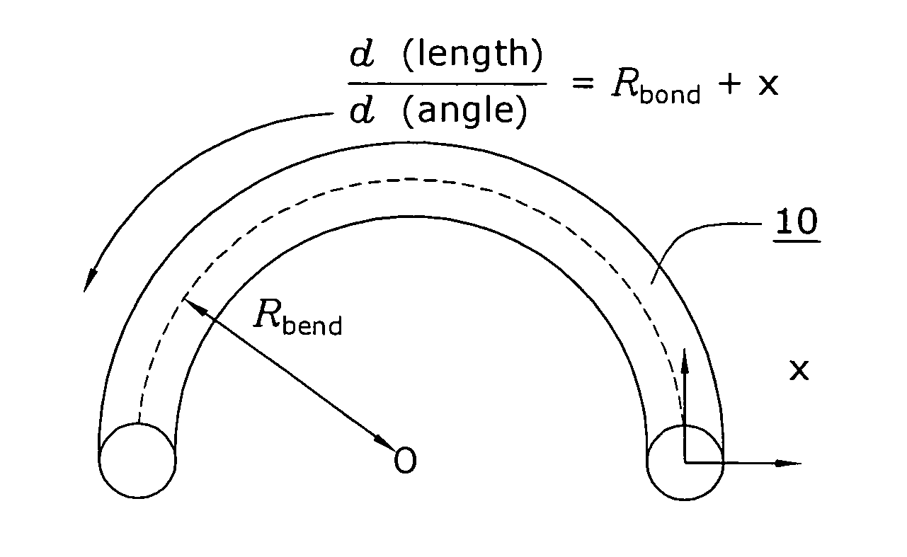
[0029]FIG. 1 illustrates an exemplary section 10 of a large core diameter optical fiber that has been bent to exhibit a defined bend radius. As shown, bent fiber 10 is defined as having a bend radius Rbend, with the x-y orientation as shown. The bending of a large core diameter optical fiber, as mentioned above, has been found to introduce distortion in the form of reduced effective area. In particular, the equivalent index model of bent fiber 10 can be determined and then analyzed to account for the different path lengths “seen” by a propagating optical signal at different transverse positions x as it travels around the bend of radius Rbend as follows: ⅆ(length)ⅆ(angle)=Rbend+x,

where path lengths are adjusted by defining the equivalent index profile neq2, neq2⁡(x,y)=n2⁡(x,y)⁢(1+2⁢ ⁢xRbend),

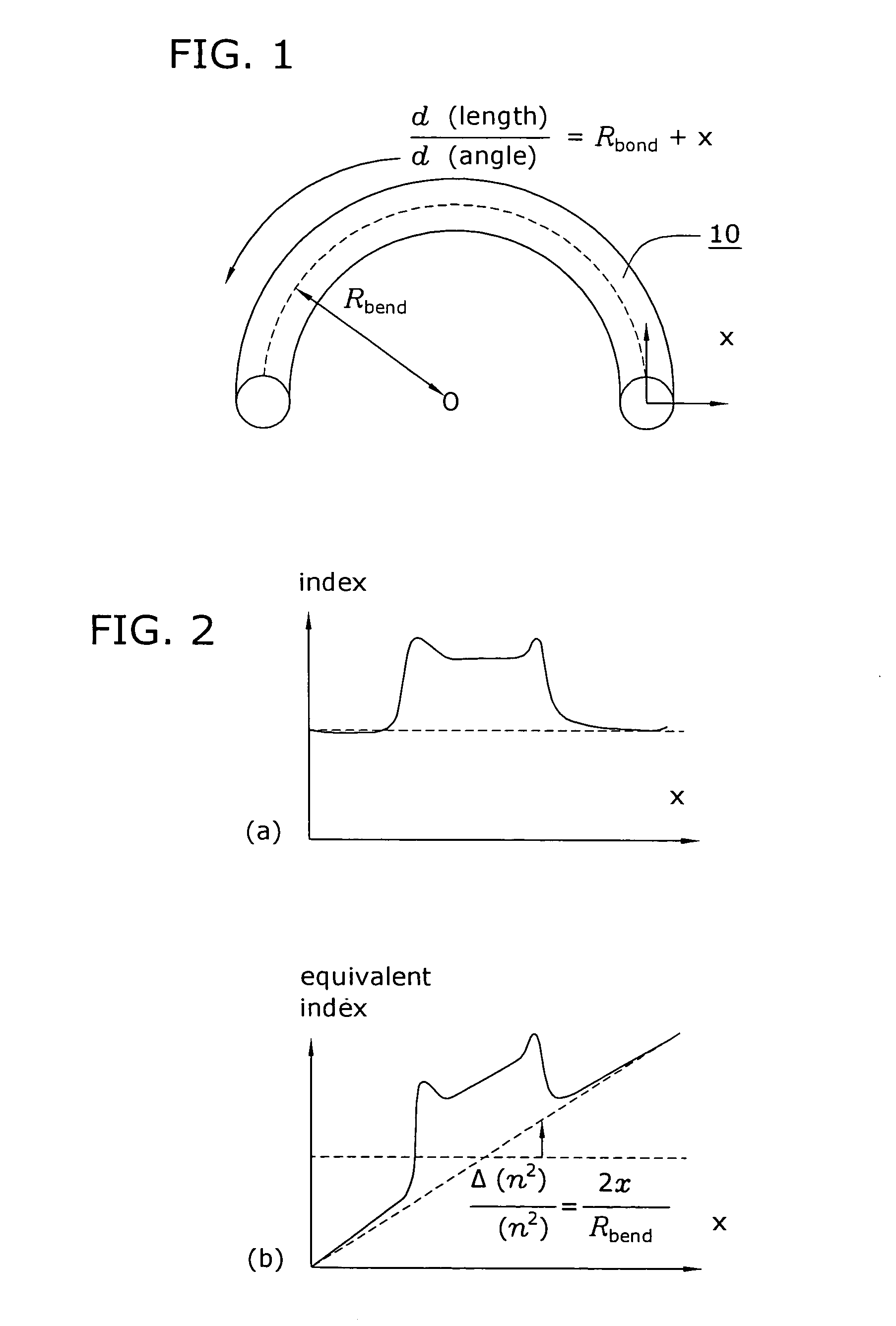
which is considered to be a modified version of the nominal refractive index profile (n2) of the optical fiber material. FIG. 2 illustrates the impact of a bend on the refractive index of fib...


PUM


Abstract

An optical fiber that exhibits reduced mode distortions as the fiber is bent is formed by properly defining its refractive index profile during fabrication. The as-fabricated profile is defined as a “pre-distorted” profile that takes into account the gradient introduced by bending the fiber. A parabolic index profile is one exemplary bend-resistant profile that exhibits a quadratic form. A raised-cone index is another profile that may be used as the “as-fabricated” profile. In any properly configured form, factors such as bend loss and mode distortion are significantly reduced, since the profile undergoes a shift of essentially constant gradient as a bend is introduced. The resultant effective area of the inventive fiber is substantially improved over state-of-the-art fiber that is subjected to bending during installation. The as-fabricated profile may be incorporated into various types of fibers (birefringent, photonic bandgap, etc.), and is particularly well-suited for use in a fiber amplifier arrangement.

Description

STATEMENT OF GOVERNMENT INTEREST IN INVENTION [0001] This invention was made with the United States Government support under the NIST ATP program, award number 70NANB4H3035, awarded by the National Institute of Standards and Technology (NIST). The United States Government has certain rights in the invention.TECHNICAL FIELD [0002] The present invention relates to large mode area optical fibers and, more particularly, to a large mode area optical fiber exhibiting a refractive index profile particularly designed to minimize the effects of bend-induced reductions in the fiber's effective area. BACKGROUND OF THE INVENTION [0003] In the field of optical fiber-based communication, there is an increasing interest in the use of large mode area fibers, particularly associated with the fabrication of fiber-based optical amplifiers and the like, since large mode area fibers are known to overcome various nonlinear impairments, such as Raman and Brillouin scattering. The use of large mode area fi...

Claims


Application Information

Patent Timeline
Patent Type & Authority Applications(United States)
IPC IPC(8): G02B6/02
CPCG02B6/02009G02B6/02023G02B6/0281G02B6/03605G02B6/14H01S3/06708
Inventor FINI, JOHN MICHAEL
Owner OFS FITEL LLC
Why Eureka
Try Eureka