
Life prediction and monitoring apparatus, life prediction and monitoring method, and life prediction and monitoring program

a monitoring apparatus and monitoring method technology, applied in lighting and heating apparatus, instruments, nuclear elements, etc., can solve the problems of failure prediction that cannot be performed stably, cannot predict the life of direct current stabilizing power supply accurately, and the reliability of measures to perform preventative replacement is declining

Inactive Publication Date: 2007-06-28
NEC CORP
View PDF5 Cites 37 Cited by
  • Summary
  • Abstract
  • Description
  • Claims
  • Application Information

AI Technical Summary

Benefits of technology

The present invention provides a life prediction and monitoring apparatus that can detect a failure occurrence of a power supply in advance and increase the reliability of preventative replacement for components. The apparatus includes a counting unit for counting the current supplying duration for a component and integrating it, a life prediction unit for predicting the life of the component based on the integrated current supplying duration and the lifetime of the component, and a monitoring unit for monitoring the efficient operating condition of the device based on the prediction signal outputted from the life prediction unit. The apparatus can be established as hardware, software or a program. The processings for counting, predicting, and monitoring are performed for each fan and component with different lifetime, so that measures to preventive replacement can be reliably implemented.

Problems solved by technology

Therefore, there is a problem in the life prediction for the direct current stabilizing power supply that measuring only for capacitor, as in Patent document 1, cannot predict the life of the direct current stabilizing power supply accurately.
Moreover, in Patent document 2, temperature in the optical disc device is managed to be maintained at a threshold with a fan, however, the optical disc device is monitored without a life prediction for the fan, so that a failure prediction cannot be performed stably.
Therefore, a life prediction is unclear, and a failure prediction of the power supply is unstable, that causes declining in reliability of measures to perform preventative replacement for components by detecting a failure occurrence of a power supply in advance.

Method used


Image

  • Life prediction and monitoring apparatus, life prediction and monitoring method, and life prediction and monitoring program
  • Life prediction and monitoring apparatus, life prediction and monitoring method, and life prediction and monitoring program
  • Life prediction and monitoring apparatus, life prediction and monitoring method, and life prediction and monitoring program

Examples


Embodiment Construction

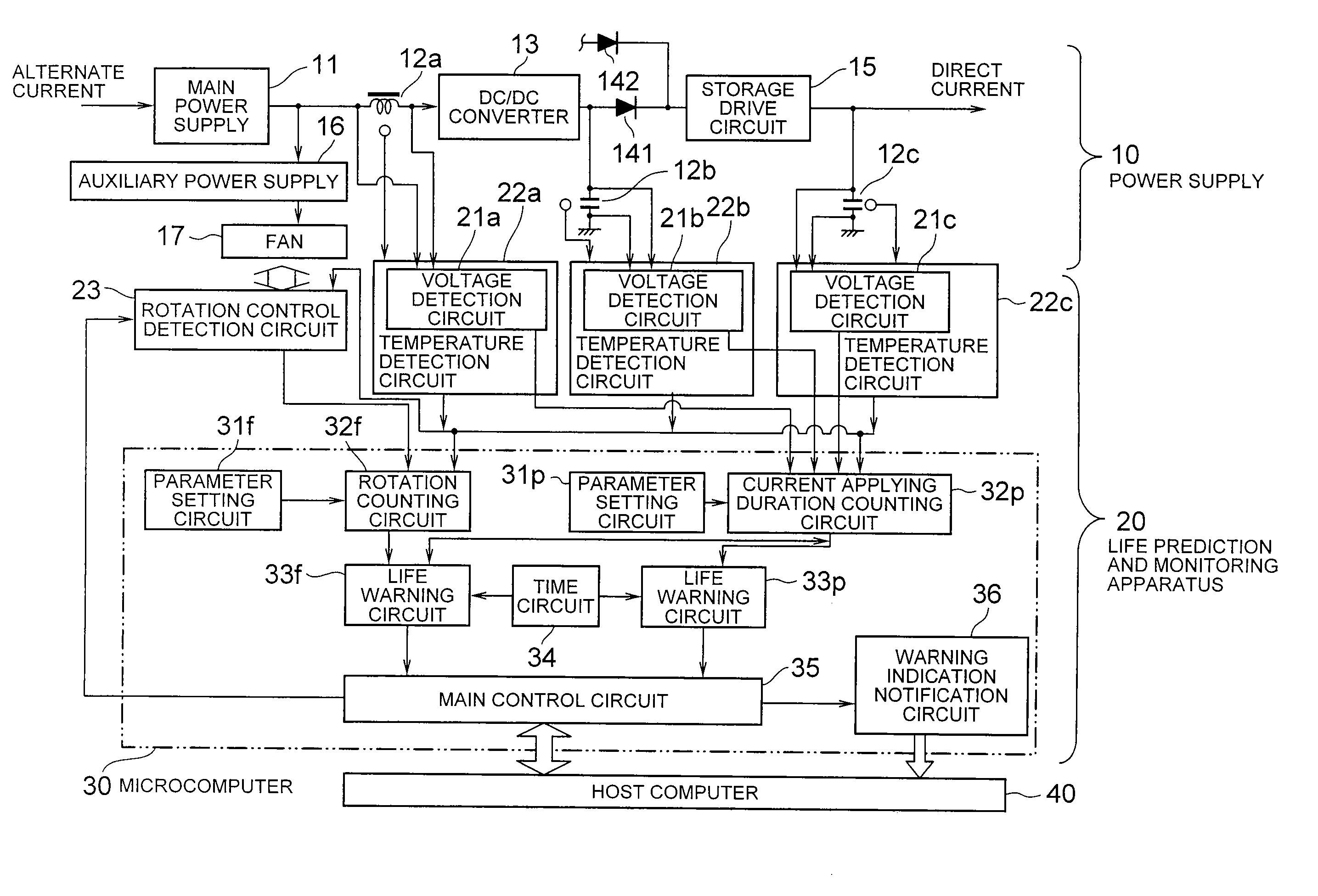
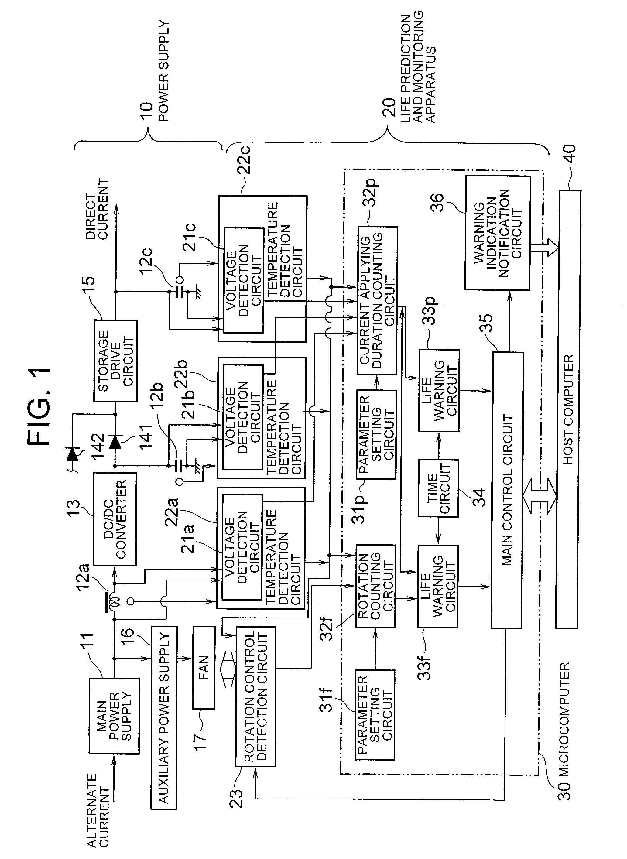
[0032] Hereinafter, an embodiment of the present invention will be explained with reference to the accompanying drawings.

[0033]FIG. 1 shows a power supply 10 comprising a life prediction and monitoring apparatus 20 according to the present embodiment. The power supply 10 shown in FIG. 1 is used as a power supply for a storage device shown in FIG. 4, while a target device for monitor is not limited to this case. The life prediction and monitoring apparatus 20 shown in FIG. 1 may be used for failure prediction to other devices than the storage device. In the followings, a case is explained with an example where the life prediction and monitoring apparatus 20 is applied to the power supply 10 of the storage device according to the present embodiment.

[0034] The power supply 10 included in the storage device comprises a main power supply 11, a coil 12a, capacitors 12b and 12c, a DC / DC converter 13, adverse current preventive diodes 141 and 142, a storage drive circuit 15, an auxiliary ...


PUM


Abstract

A counting unit counts a current supplying duration for a component which determines a life of a device. A prediction unit predicts the device life based on an integrated current supplying duration integrated by the counting unit and a lifetime of the component. A monitoring unit monitors an efficient operating condition of the device based on a prediction signal outputted from the life prediction unit. The counting unit and the life prediction unit is provided at a short-life fan and a long-life component respectively, and the life prediction unit predicts the life of the device based on information on the short-life fan and the long-life component.

Description

1. FIELD OF THE INVENTION [0001] The present invention relates to a life prediction and monitoring apparatus for predicting a life of a component which determines a life of an electrical equipment or an electronic device (hereinafter, called a device), and monitoring an efficient operating condition of the device. 2. DESCRIPTION OF THE RELATED ART [0002] A life prediction and monitoring apparatus has been developed for predicting lives of components, which determine lives of devices, so as to monitor efficient operating conditions of the devices. Here, the efficient operating condition of a device means that the substantial operating period remaining for the device to work within its residual life. As shown in FIG. 5, a conventional life prediction and monitoring apparatus (in the Japanese Patent Laid Open 11-356036, Patent document 1, for example) 80 comprises a parameter setting circuit 82, a life prediction circuit 83, a nonconformity output circuit 84, a life detection circuit 8...

Claims


Application Information

Patent Timeline
Patent Type & Authority Applications(United States)
IPC IPC(8): G06F15/00G06F11/30
CPCG06F11/008
Inventor WARIZAYA, KANJI
Owner NEC CORP
Learn More