Ultrasonic-densiometer mass flow sensor for use in flow metering units

a technology of mass flow sensor and ultrasonic densiometer, which is applied in the direction of liquid/fluent solid measurement, machines/engines, instruments, etc., can solve the problems of high cost and complexity of conventional fuel delivery systems for gas turbine engines, complicated fuel metering valves, and other components, and achieve accurate mass flow rate information.

Inactive Publication Date: 2007-07-05
HAMILTON SUNDSTRAND CORP
View PDF12 Cites 27 Cited by
  • Summary
  • Abstract
  • Description
  • Claims
  • Application Information

AI Technical Summary

Benefits of technology

[0008] Accordingly, the present invention provides a fuel metering unit that eliminates the fuel metering valve, dual rotor turbine meter, linear variables displacement transducer, and other complicated and expensive components typically found in prior art fuel delivery systems, while providing accurate mass flow rate information.

Problems solved by technology

Conventional fuel delivery systems for gas turbine engines are expensive and include numerous complex parts.
The dual rotor turbine meter is a volumetric device with limited accuracy, therefore it is not used for engine health monitoring.
The fuel metering valve, dual rotor turbine meter, linear variable displacement transducer, pressure regulator, and other components, are all quite complicated.
The metering valve also creates a pressure drop within the system that generates extra heat in fuel and decreases the efficiency of the oil cooling system.

Method used


Image

  • Ultrasonic-densiometer mass flow sensor for use in flow metering units
  • Ultrasonic-densiometer mass flow sensor for use in flow metering units
  • Ultrasonic-densiometer mass flow sensor for use in flow metering units

Examples


Embodiment Construction

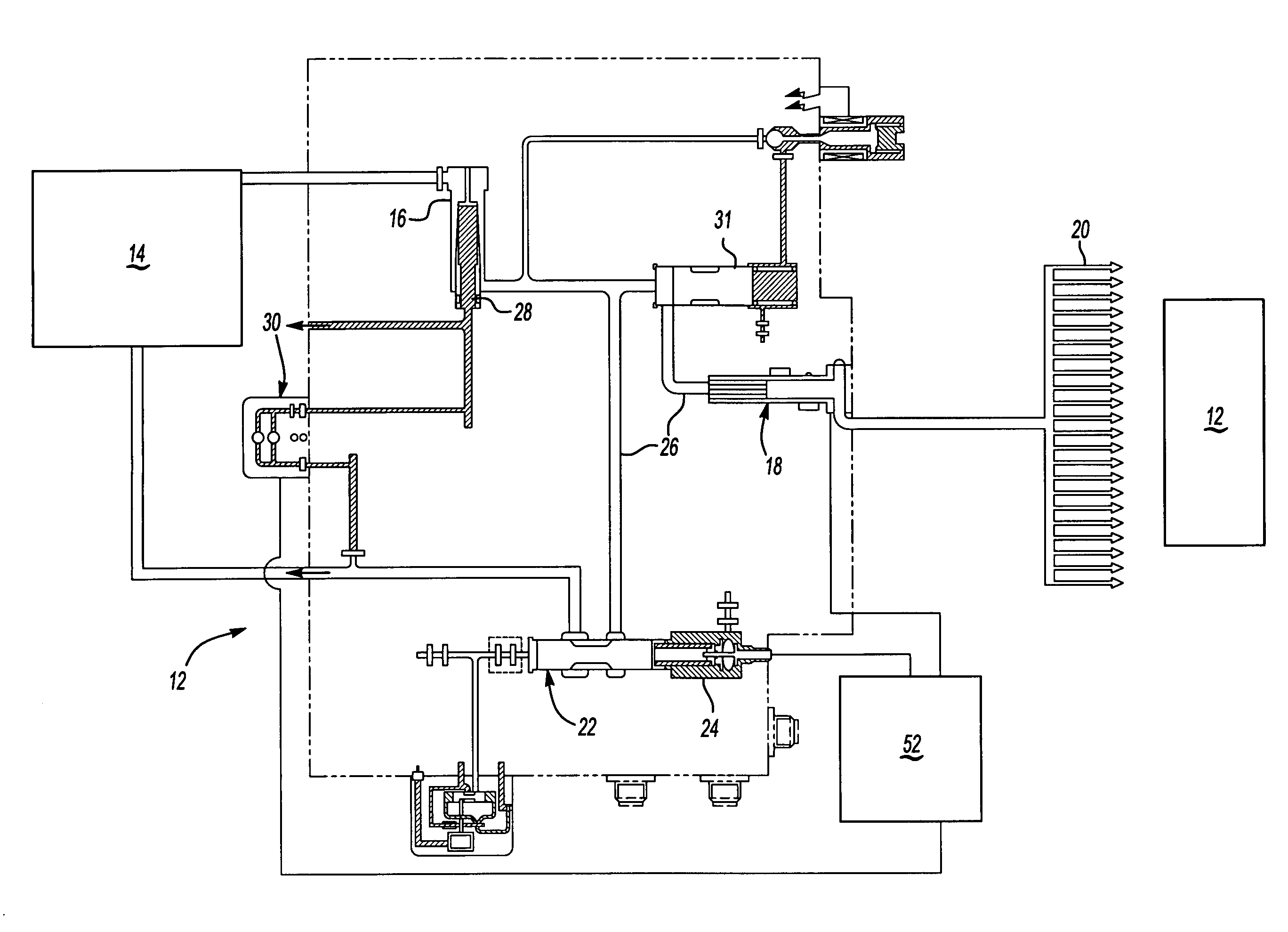
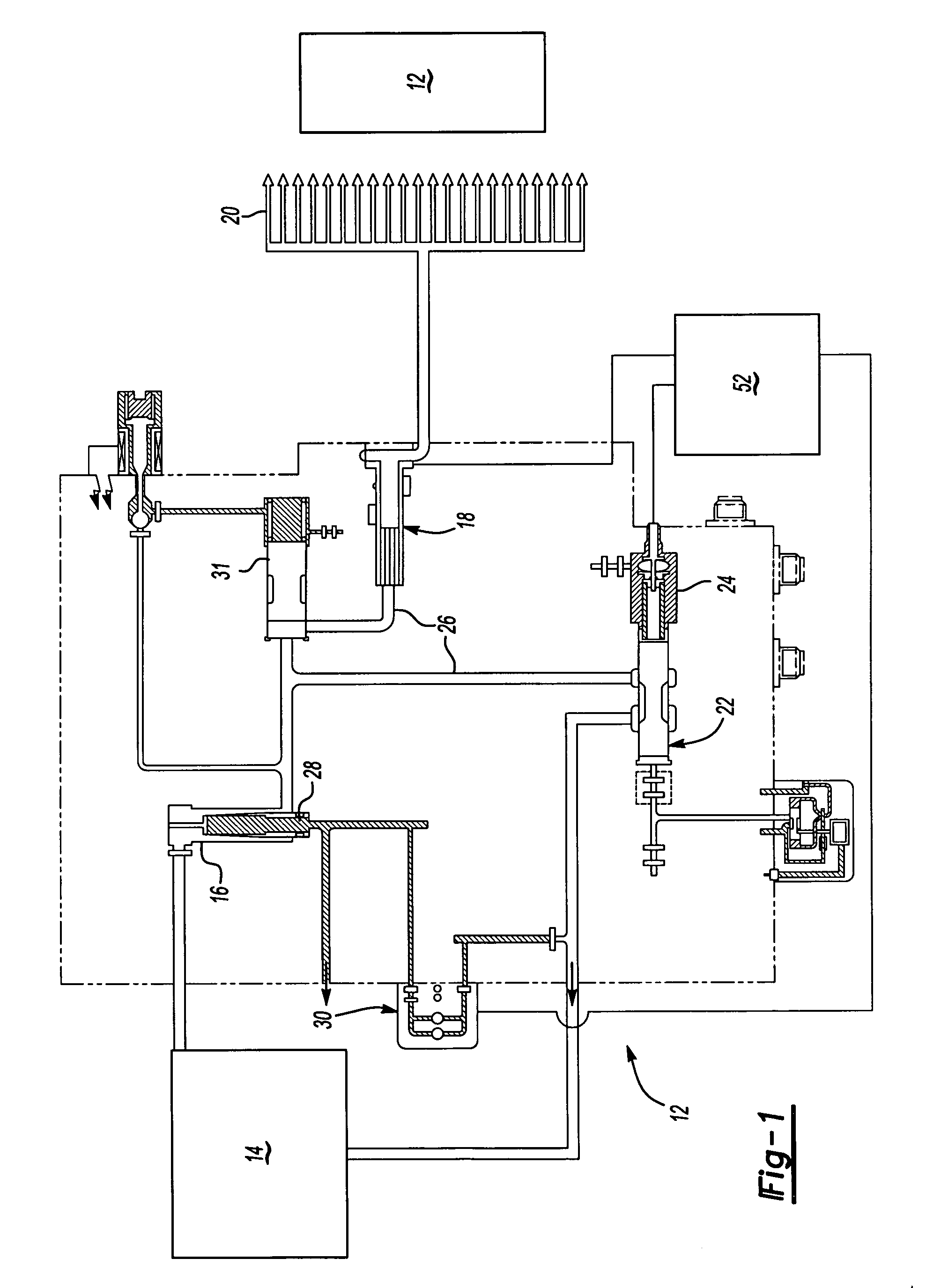
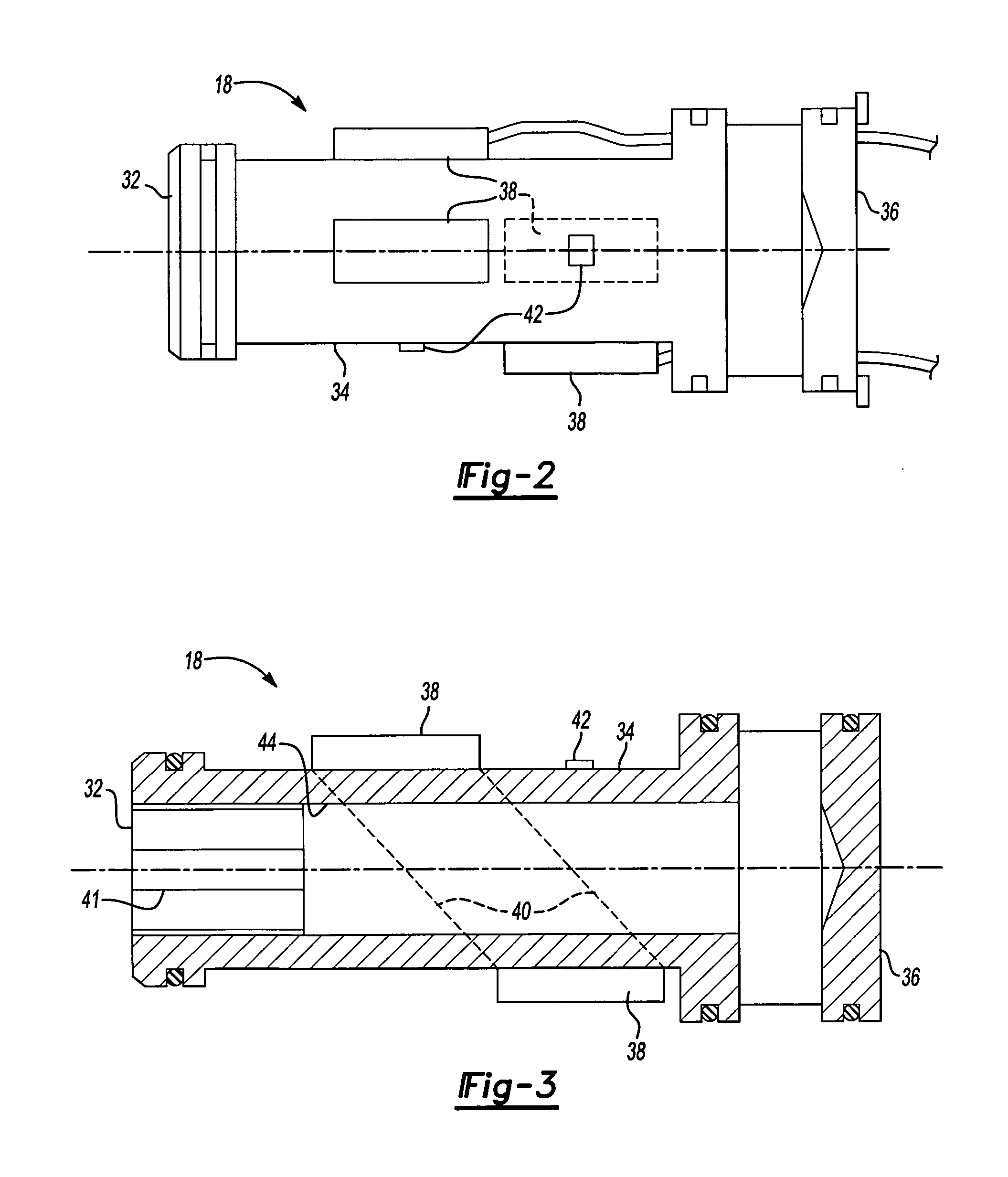
[0016] A fuel delivery system 10 is shown schematically in FIG. 1. The system 10 is preferably for use in delivering fuel to a gas turbine engine 12. Fuel from a boost pump system 14 passes through a fuel filter 16. The fuel flows from the fuel filter 16 through an ultrasonic volumetric flow sensor 18 and is discharged from fuel nozzles 20 into the engine 12. Due to the ability of the ultrasonic flow sensor 18 to withstand high temperatures, it may be located immediately prior to the fuel nozzles 20 as shown in the present embodiment. However, other locations for the ultrasonic flow sensor 18 can also be utilized to provide volumetric flow information.

[0017] Between the fuel filter 16 and the ultrasonic flow sensor 18 a portion of the fuel is directed toward a pressure-regulating valve 24 which can be used to adjust the fuel pressure in the fuel line 26 prior to the fuel nozzles 20. By decreasing pressure within the fuel line 26 the flow rate of the fluid through the ultrasonic flo...


PUM


Abstract

A fuel delivery system uses a volumetric flow sensor and a densiometer to measure a mass flow rate of the fuel. A densiometer may be a coriolis mass flow sensor etched into a small circuit chip. As fuel flows past the densiometer a density of the fuel and characteristic slope as a function of temperature is determined. At least one temperature sensor is also located on the circuit chip to provide accurate temperature of the fuel to correspond to the fuel density reading. Piezoelectric crystals in the volumetric flow sensor generate and receive a sound wave. By analyzing the sound wave signals the volumetric flow rate of fluid through the volumetric flow sensor can be calculated. At least one temperature sensor is also placed on the volumetric flow sensor to correct for any thermal expansion of an inner diameter of the volumetric flow sensor and for final mass flow calculation. The density and temperature information from the densiometer and the volumetric flow and temperature information from the volumetric flow sensor are used to determine the density of the fuel at the volumetric flow sensor. By using the density calculated at the volumetric flow sensor and using the volumetric flow information an accurate mass flow rate of the fuel at the volumetric flow sensor can be calculated.

Description

BACKGROUND OF THE INVENTION [0001] This invention relates to a pressure regulating fuel delivery system suitable for a gas turbine engine, having a pressure regulator, together with an ultrasonic sensor and a densiometer to accurately measure the mass flow of fuel to the engine. [0002] Conventional fuel delivery systems for gas turbine engines are expensive and include numerous complex parts. A typical fuel delivery system is controlled by scheduling fuel flow based upon a fuel metering valve position and a linear variable displacement transducer to provide feedback. The metering valve position is adjusted in closed loop to maintain the desired engine speed (and power setting). A low accuracy dual rotor turbine meter to measure totalized mass flow after the fuel metering unit. The totalized flow is used as a double check for the wing tank fuel level gauges. The dual rotor turbine meter is a volumetric device with limited accuracy, therefore it is not used for engine health monitorin...

Claims


Application Information

Patent Timeline
Patent Type & Authority Applications(United States)
IPC IPC(8): G01M19/00G01M99/00
CPCF01D17/08F02C9/26G01F1/667F05D2270/30G01F1/86F05D2270/303G01F1/8445
Inventor PARADISE, BRUCE
Owner HAMILTON SUNDSTRAND CORP
Why Eureka
Try Eureka