Reloadable non-lethal training cartridge
- Summary
- Abstract
- Description
- Claims
- Application Information
AI Technical Summary
Benefits of technology
Problems solved by technology
Method used
Image
Examples
third embodiment
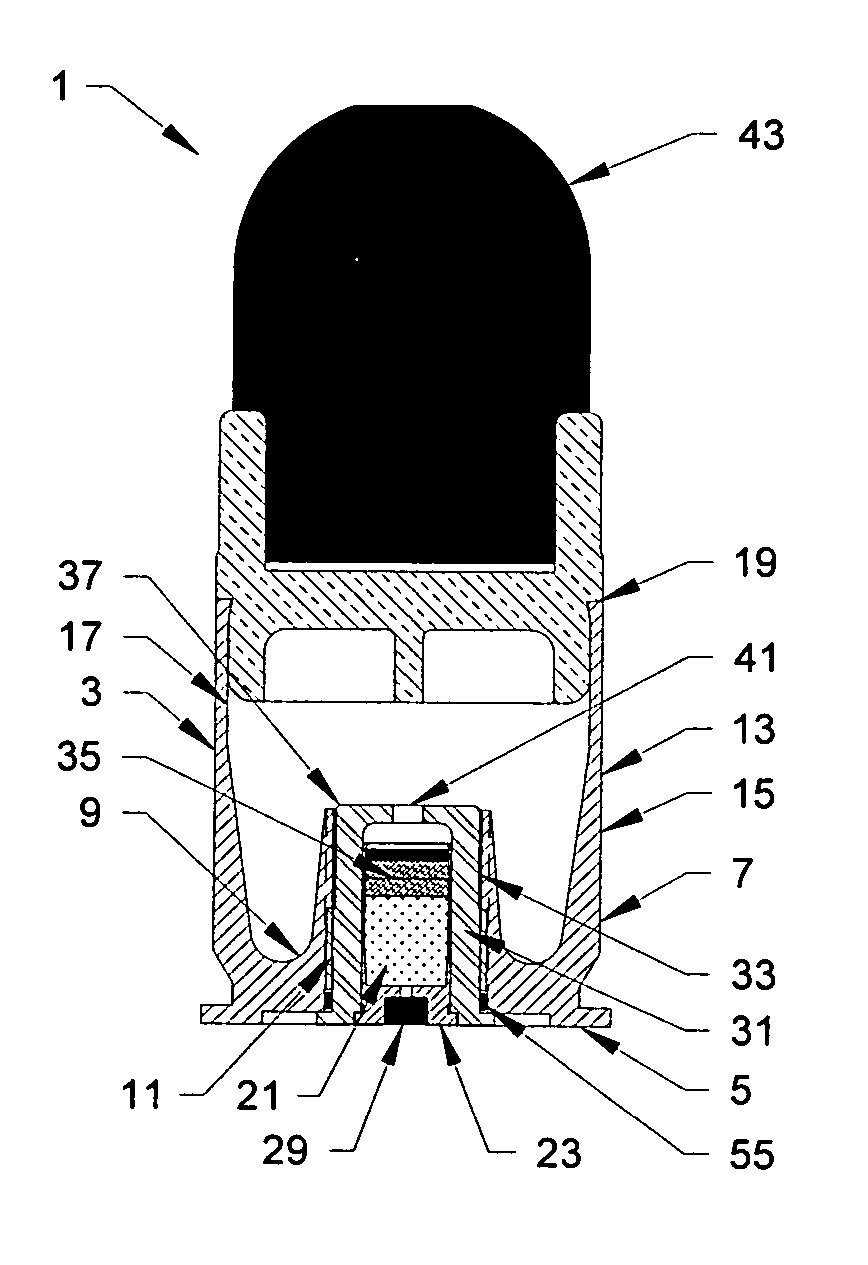
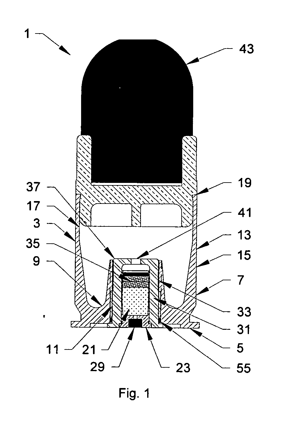
[0060] In a further embodiment of the rear high pressure chamber, as called for in the third embodiment herein, and as illustrated in FIG. 3, a washer 65 is removably disposed within the interior portion 35 of the circumferential portion 31 of the rear high pressure chamber 21, adjacent the forward end 37 thereof. The washer 65 has an aperture 67 smaller than the outer circumference 41 of the propellant vent hole, so as to restrict the release of high pressure propellant gases into the interior portion of the cartridge 3. The diameter of the aperture 65 may be adjusted (chosen prior to use) to alter the firing characteristics of the non-lethal payload portion 43. In particular, by decreasing the diameter of the aperture 65, the firing of the non-lethal payload portion 43 may be delayed.
[0061] A firing blank insertion aperture 29 is disposed through said base 23, within the outer circumference 25, so as to allow for the insertion of firing blanks into the rear high pressure chamber. ...
sixth embodiment
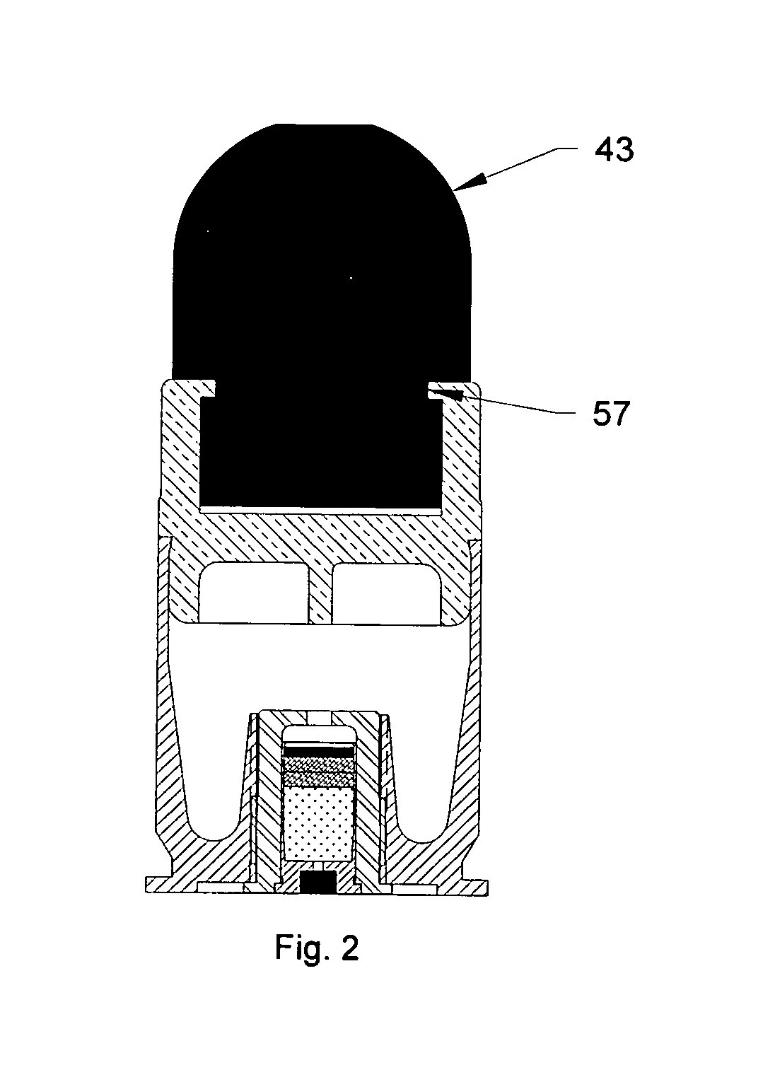
[0065] For example, frictional engagement means 57, as called for in the sixth embodiment herein, and as illustrated in FIG. 2, consisting of a ridge formed on the circumferential portion 51 and / or the non-lethal payload 53, may be utilized to removably attach the base 45 to the non-lethal payload 53, so that the base 45 and / or the non-lethal payload 53. Alternatively, as shown in FIG. 4, threads 59 may be provided on the circumferential portion 51 of the base 45, so as to engage threads formed on the non-lethal payload 43.
[0066] Alternatively, the base 45 may be fixedly attached to the non-lethal payload 43, by adhering the non-lethal payload to the base 45 with an adhesive. When fixedly attached, the longevity of the non-lethal payload portion is dependent upon the condition of both the base 45 and the non-lethal payload 53. In contrast, when the base 45 is removably attached to the non-lethal payload 53, if one component is damaged during use, only that component need be replaced...
eleventh embodiment
[0068] In a further embodiment of the non-lethal payload portion, as called for in the eleventh embodiment herein, and as illustrated in FIG. 5, the hollow portion 61 of the non-lethal payload 43 may be filled with a weighted material 71, such as lead pellets, shot, etc. In FIG. 5, the weighted material 71 is lead shot. It was unexpectedly discovered by the present inventor that by weighting the non-lethal payload 43 with the weighted material 71, accuracy was dramatically increased at extended ranges of, for example, about 50 meters.
[0069] As called for in the sixteenth and seventeenth embodiments of the present invention, and as illustrated in FIG. 8 herein, a rotating band 69 is provided, which is disposed around the circumferential portion 51 of the base 45 of the non-lethal payload portion 43. This rotating band 69 interacts with the barrel rifling groove of the weapon used to fire the cartridge 1, so as to impart a spin to the non-lethal payload portion 43 when fired. The spin...
PUM
 Abstract
Description
Claims
Application Information
 - R&D
- Intellectual Property
- Life Sciences
- Materials
- Tech Scout
- Unparalleled Data Quality
- Higher Quality Content
- 60% Fewer Hallucinations
Browse by: Latest US Patents, China's latest patents, Technical Efficacy Thesaurus, Application Domain, Technology Topic, Popular Technical Reports.
© 2025 PatSnap. All rights reserved.Legal|Privacy policy|Modern Slavery Act Transparency Statement|Sitemap|About US| Contact US: help@patsnap.com


