Reversible hydraulic pressure converter employing tubular valves

a hydraulic pressure converter and tubular valve technology, which is applied in the direction of propulsive elements, high-tension/heavy-dress switches, vessel construction, etc., can solve the problems of inability to recover all of the compression energy of hydraulic fluid, the pump/motor is optimized, and the pressure of the hydraulic flow is technologically more difficult to reduce. , to achieve the effect of high operational pressure, excellent efficiency and optimized pump/motor efficiency

Active Publication Date: 2015-02-26
RABHI VIANNEY
View PDF4 Cites 27 Cited by
  • Summary
  • Abstract
  • Description
  • Claims
  • Application Information

AI Technical Summary

Benefits of technology

[0024]This would notably make it possible to optimize the efficiency of said pump / motor, the latter being connected to the high pressure only when used at high powers and remaining connected to the low pressure when used at low powers.
[0025]This principle would advantageously be combined, for example, with the pump / motor described in the applicant's U.S. Pat. No. 1,354,562 of 22 May 2013, said pump / motor being compatible with ultra-high-pressures of the order of two thousand bar. Subject at least to the technical configuration described in said patent, this high operational pressure would enable said pump / motor to deliver excellent efficiency, at least when said pump / motor is used at not less than half cubic capacity. Below half cubic capacity, at high pressures, the efficiency of said pump / motor is inevitably degraded because of an increasing fraction of the unrecoverable fraction of the work done to compress the oil and high friction losses relative to the useful work transmitted. Therefore, at low powers, utilizing—on the pump / motor side—a lower pressure to store and return energy would notably improve the overall efficiency of a hydraulic hybrid transmission based on said pump / motor.

Problems solved by technology

Note that it is technologically more difficult to amplify or to reduce the pressure of a hydraulic flow that must be continuous than to amplify or to reduce the pressure of a hydraulic flow where a discontinuous flow is acceptable.
On the other hand, their principal disadvantage is their pulsed operation and, to a lesser degree, the fact that they cannot recover all of the compression energy of the hydraulic fluid, particularly on the sender piston side.
The problem of pressure amplifiers or reducers employing rotary positive displacement hydraulic pumps is their cost, their complexity, their overall size and their efficiency, which is generally lower than that of pressure amplifiers or reducers employing pistons.
These variants are therefore not reversible to enable pressure reduction, and the pressure amplifiers as described in the patents FR 2889265, FR 2575792 and U.S. Pat. No. 5,984,026 are not reversible either.
This is because the high-pressure stage operates only as a pump and is not equipped with a switch, while the low-pressure stage is designed only to operate as a driver, its switching device not being intended to enable said low-pressure stage to operate as a pump.
Note moreover that the high-pressure stage would with difficulty accommodate switches employing slide valves or ports as employed in the various patents described above because the ultra-high-pressures usually required mean that any leakage at the level of the slide valves or ports compromises efficiency, whether said leaks occur during the maneuver to open or block said slide valves or ports or while the latter are held closed, being by their nature imperfectly sealed at ultra-high-pressures.
It would then be necessary to provide actuators employing valves, needle valves or ball valves because these devices are inherently fluid-tight, although they generate high maneuvering forces.

Method used


Image

  • Reversible hydraulic pressure converter employing tubular valves
  • Reversible hydraulic pressure converter employing tubular valves
  • Reversible hydraulic pressure converter employing tubular valves

Examples


Embodiment Construction

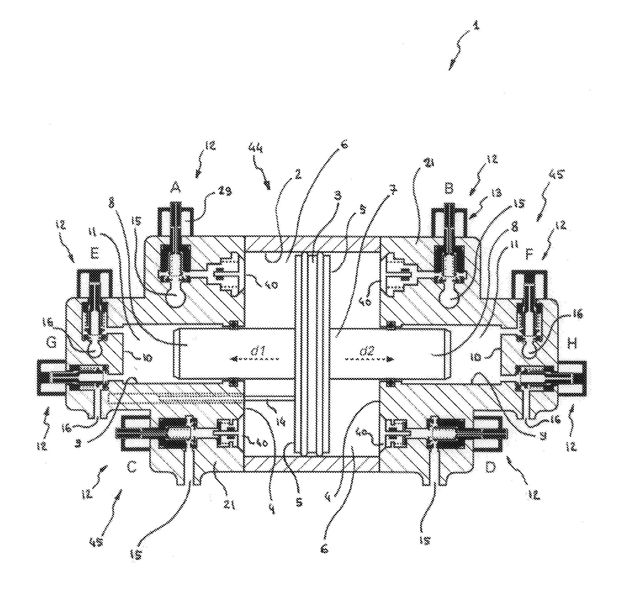
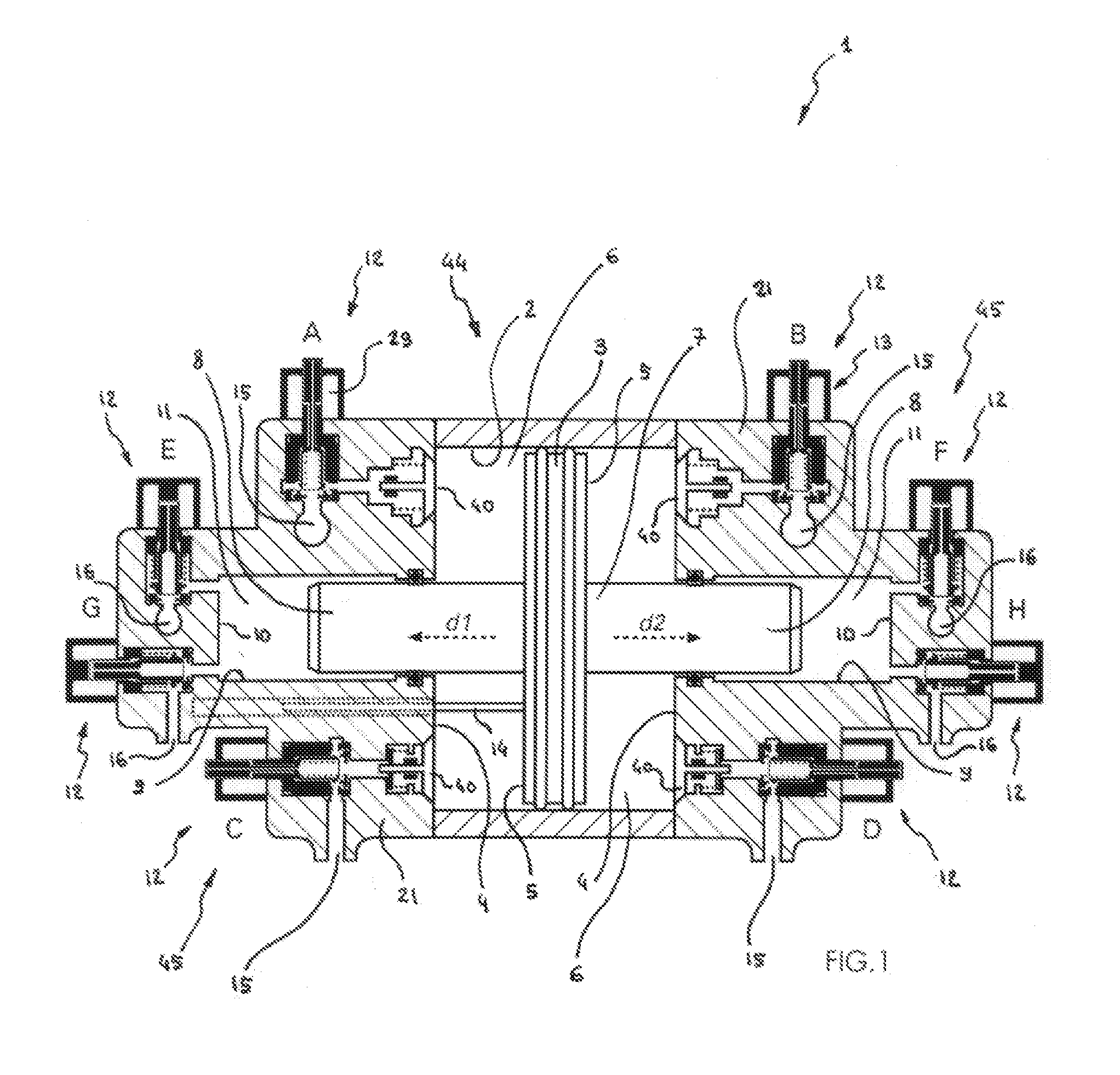
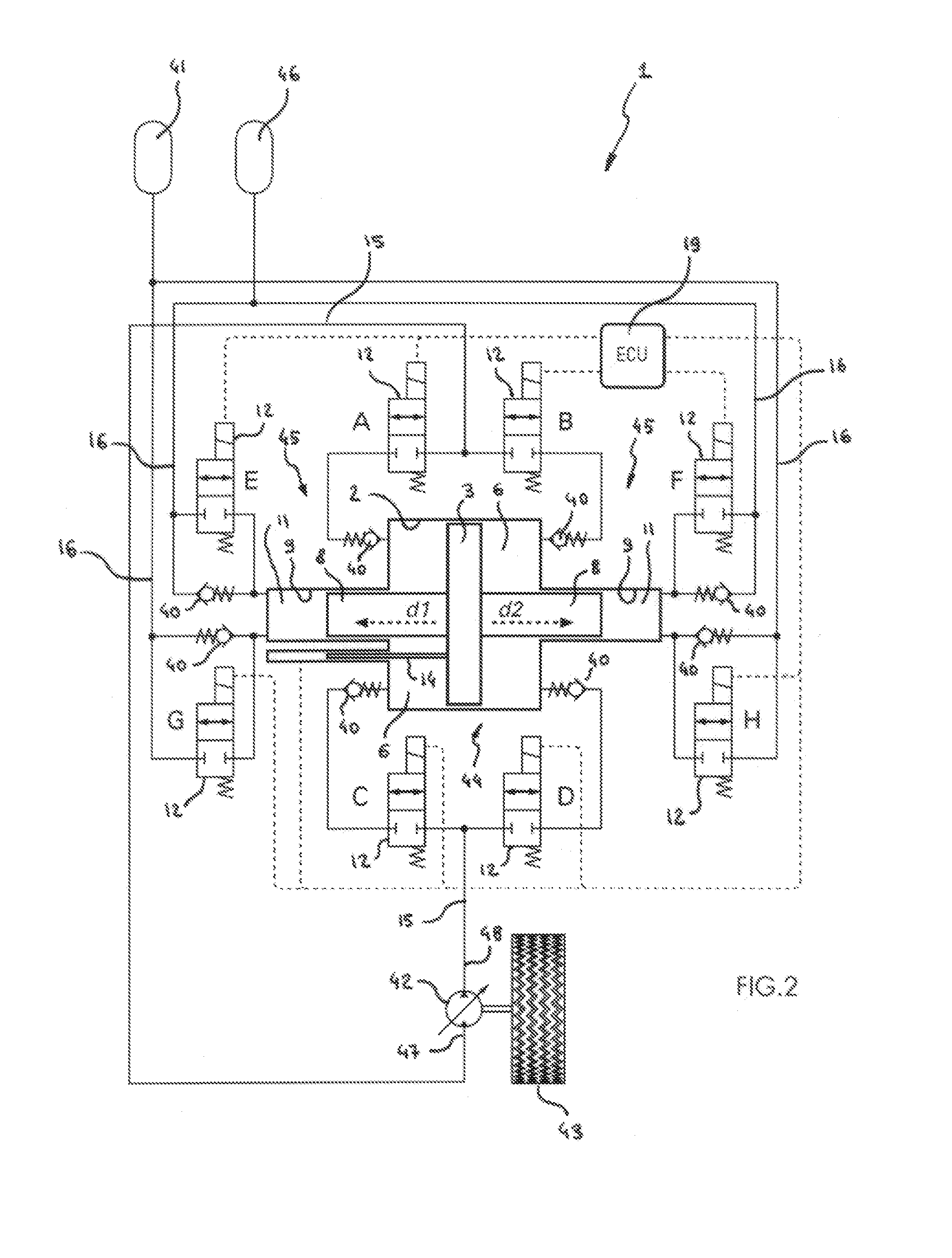
[0067]The reversible hydraulic pressure converter 1 employing tubular valves is shown in FIGS. 1 to 8.

[0068]It is seen—particularly in FIG. 1—that the reversible hydraulic pressure converter 1 in accordance with the invention employing tubular valves includes a medium-pressure stage 44 consisting of a medium-pressure cylinder 2 each of the two ends of which is closed by a medium-pressure head 4 and in which can move in translation in a fluid-tight manner a double-acting medium-pressure piston 3 that has a pressure face 5 facing each medium-pressure head 4 while said cylinder 2, said heads 4 and said pressure faces 5 form two medium-pressure chambers 4 positioned axially on respective opposite sides of the double-acting medium-pressure piston 3.

[0069]Note that the double-acting medium-pressure piston 3 may be provided with at least one ring or at least one seal of any type known to the person skilled in the art. The pressure converter 1 in accordance with the invention further includ...


PUM


Abstract

The reversible hydraulic pressure converter (1) employing tubular valves includes a medium-pressure stage (44) consisting of a medium-pressure cylinder (2) and a double-acting medium-pressure piston (3) the position of which is sent to a control computer of the converter (19) by a piston position sensor (14), the cylinder (2) and the piston (3) forming two medium-pressure chambers (5) that can be placed in communication with a medium-pressure inlet-outlet circuit (15) by at least one tubular valve (12), the converter (1) also including two high-pressure cylinders (9) each cooperating with a high-pressure piston (8) of smaller diameter and defining two high-pressure chambers (11) that can be placed in communication with a high-pressure inlet-outlet circuit (16) by at least one tubular valve (12), each of the various tubular valves (12) cooperating with an independent valve actuator (13).

Description

FIELD OF THE INVENTION[0001]The subject matter of the present invention is a reversible hydraulic pressure converter employing tubular valves.BACKGROUND OF THE INVENTION[0002]There exist various technological solutions for amplifying and / or reducing the pressure of a hydraulic circuit. Note that it is technologically more difficult to amplify or to reduce the pressure of a hydraulic flow that must be continuous than to amplify or to reduce the pressure of a hydraulic flow where a discontinuous flow is acceptable.[0003]The dominant principle on which most pressure amplifiers or reducers rely consists in a sender piston rigidly connected to a receiver piston, said two pistons moving over the same stroke and having different sections. In this case, each piston cooperates with a cylinder and a head while the sender piston communicates with a hydraulic circuit independent of that of the receiver piston. To increase the pressure, the sender piston must have a larger section than the recei...

Claims


Application Information

Patent Timeline
Patent Type & Authority Applications(United States)
IPC IPC(8): F15B3/00F03C1/007
CPCF03C1/0073F15B3/00F03C1/0076F04B9/113F15B1/024
Inventor RABHI, VIANNEY
Owner RABHI VIANNEY
Why Eureka
Try Eureka