Internal combustion engine with a precombustion chamber

Inactive Publication Date: 2007-07-05
NISSAN MOTOR CO LTD
View PDF9 Cites 29 Cited by
  • Summary
  • Abstract
  • Description
  • Claims
  • Application Information

AI Technical Summary

Benefits of technology

[0012] Preferably, residual gas in the auxiliary combustion chamber at the time of ignition can be reduced,

Problems solved by technology

However, in the related engine, the auxiliary combustion chamber may tend to cause a poor torch jet (that is, u

Method used


Image

  • Internal combustion engine with a precombustion chamber
  • Internal combustion engine with a precombustion chamber
  • Internal combustion engine with a precombustion chamber

Examples


Embodiment Construction

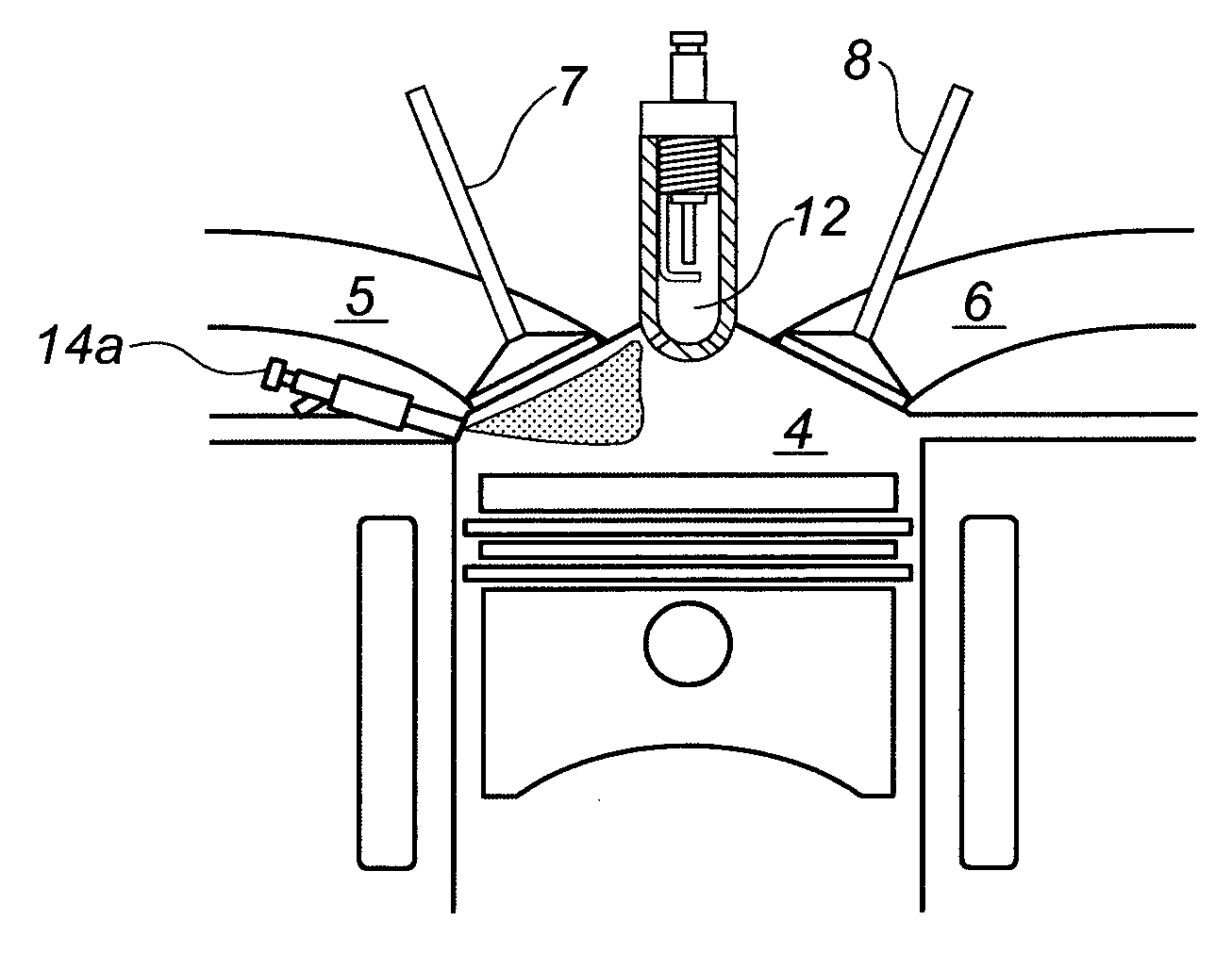
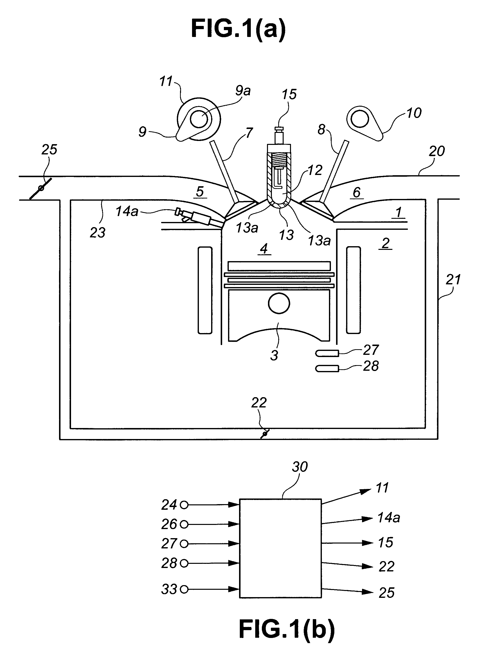
[0045]FIG. 1(a) shows a schematic view of an internal combustion engine (“ICE”). A cylinder head 1, a cylinder block 2, and a piston 3 define a main combustion chamber (also called a “main chamber”) 4. The main combustion chamber 4 is connected to an intake port 5 through an intake valve 7, and connected to an exhaust port 6 through an exhaust valve 8.

[0046] Intake valve 7 and exhaust valve 8 are driven to open and close by an intake cam 9 and exhaust cam 10, respectively. A variable valve timing mechanism 11 is coupled to an end portion of an intake cam shaft 9a to which intake cam 9 is connected. The variable valve timing mechanism 11 may vary the phase of intake cam 9 during operation of the engine. As it is used herein, “phase” relates to the open / close timing of intake valve 7.

[0047] An intake passage 23 is connected upstream of intake port 5. Although not shown in FIG. 1(a), an intake collector and an air filter, which removes particulates from the intake air, may be dispose...


PUM


Abstract

An internal combustion engine includes neighboring main and auxiliary combustion chambers that are separated by a partition wall including a communicating passage. Ignition of an air/fuel mixture in the auxiliary combustion chamber produces a fuel torch that is jetted into an air/fuel mixture in the main combustion chamber. Under a predetermined operation condition, timing for opening an intake valve is retarded relative to both the timing for closing an exhaust valve and the timing for top dead center of a piston on an exhaust stroke. By retarding the timing for opening the intake valve, residual gas in the auxiliary combustion that is left over from a previous cycle can be reduced.

Description

CROSS-REFERENCE TO RELATED APPLICATIONS [0001] This application claims priority under 35 U.S.C. § 119 to Japanese Patent Application No. 2005-361758, filed on Dec. 15, 2005, the disclosure of which is incorporated by reference herein in its entirety. BACKGROUND OF THE INVENTION [0002] 1. Field of the Invention [0003] The invention relates to an internal combustion engine having a main combustion chamber and an auxiliary combustion chamber, and more particularly to a technique for obtaining stable combustion with a relatively simple construction. [0004] 2. Description of Related Art [0005] A related engine has an auxiliary combustion chamber in addition to a main combustion chamber. A torch like flame (also called a “fuel torch”) is produced by igniting an air / fuel mixture in the auxiliary combustion chamber. The fuel torch is jetted into the main combustion chamber to shorten and stabilize the combustion process. [0006] However, in the related engine, the auxiliary combustion chambe...

Claims


Application Information

Patent Timeline
IPC IPC(8): F02B19/10F02B19/14
CPCF02B19/12F02B23/101Y02T10/18F02D13/0265Y02T10/125F02B23/104Y02T10/12
Inventor TAKAHASHI, EIJINODA, TORUKAKUHO, AKIHIKOHOTTA, ISAMUASHIDA, KOICHI
Owner NISSAN MOTOR CO LTD
Why Eureka
Try Eureka