Eureka AIR delivers breakthrough ideas for toughest innovation challenges, trusted by R&D personnel around the world.

Method and apparatus for controlling materials quality in rolling, forging, or leveling process

a technology of material quality and rolling process, applied in the direction of measuring device, paper/cardboard container, envelope/bag making machinery, etc., can solve the problem of too large to change the actual adding rate of each product, the material quality cannot be obtained, and the lot size of products during quality governing, so as to prevent the occurrence of material quality estimation errors and maintain the effect of material quality

Active Publication Date: 2007-07-05
TOSHIBA MITSUBISHI-ELECTRIC IND SYST CORP
View PDF3 Cites 29 Cited by
  • Summary
  • Abstract
  • Description
  • Claims
  • Application Information

AI Technical Summary

Benefits of technology

[0041] According to the present invention, quality of a material at a measuring position by a materials quality sensor can be controlled for matching to target data. The materials subsequently processed also become controllable so that quality of each material at a measuring position by the materials quality sensor will match to target data. In addition, materials quality estimation errors due to variations in materials quality at the materials quality sensor position can be prevented from occurring, and the materials quality at a materials quality control point can be matched to target data. Furthermore, it is possible to prevent the occurrence of materials quality estimation errors due to variations in materials quality at the materials quality sensor position, and to maintain constant materials quality at a materials quality control point.

Problems solved by technology

The lot sizes of products during quality governing, however, are too great to change an actual adding rate for each product.
In recent years, however, the significantly growing sophisticatedness and diversity of the product specifications called for have caused a case in which the desired materials quality cannot be obtained because of appropriate target data not always being determined using such an experiential method.

Method used


Image

  • Method and apparatus for controlling materials quality in rolling, forging, or leveling process
  • Method and apparatus for controlling materials quality in rolling, forging, or leveling process
  • Method and apparatus for controlling materials quality in rolling, forging, or leveling process

Examples


first embodiment

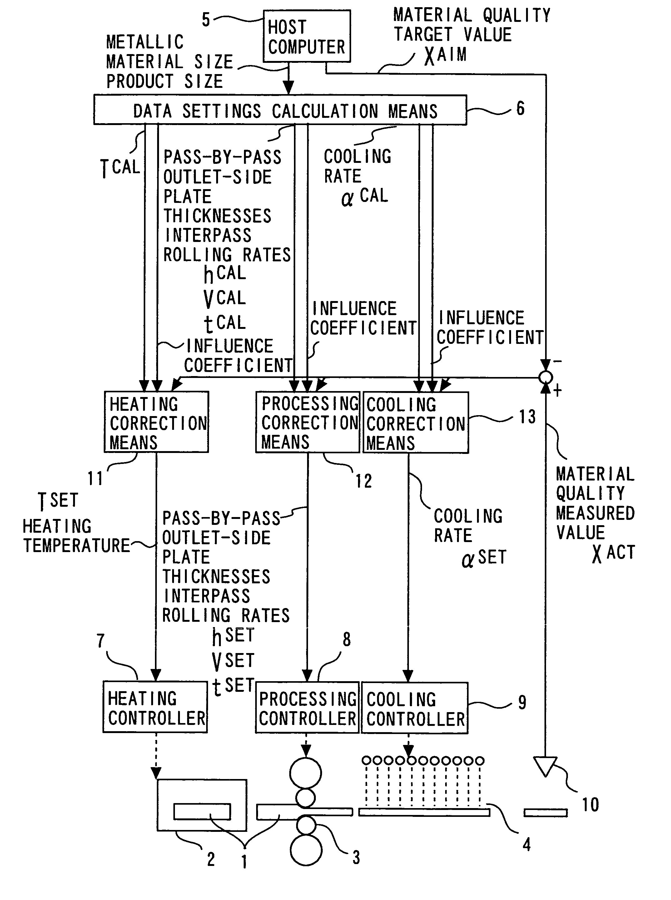
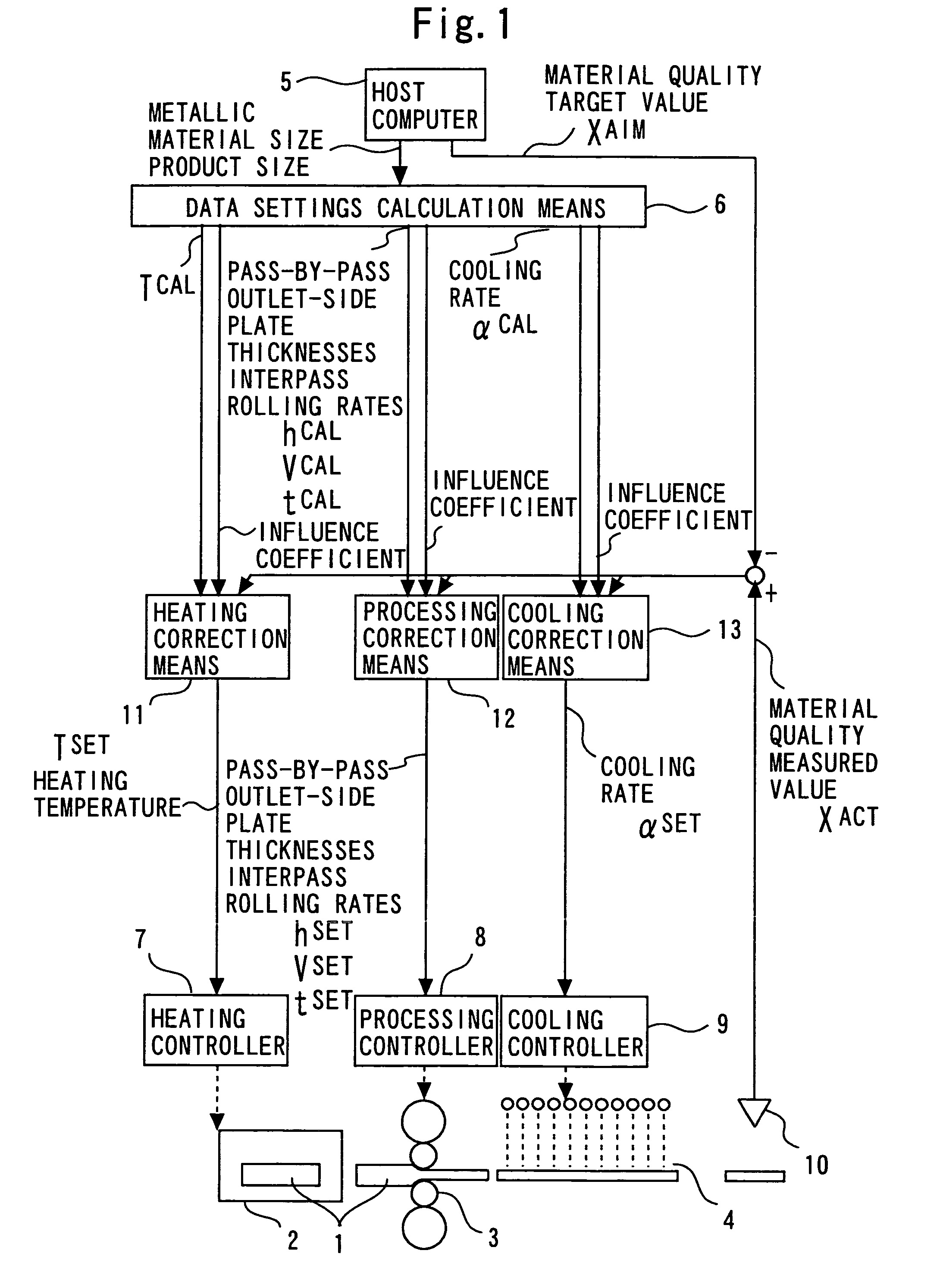
[0066]FIG. 1 is a block diagram showing a method and apparatus for controlling materials quality in a rolling, forging, or leveling process according to a first embodiment of the present invention.

[0067] Operation of a data settings calculation means 6, a heating controller 7, a processing controller 8, a cooling controller 9, a heater 2, a processor 3, and a cooler 4, is the same as in the conventional method and apparatus underlying the present invention.

[0068] A materials quality sensor 10 is installed at any position downstream with respect to at least one of the heater 2, processor 3, and cooler 4 in an associated manufacturing line. The heater 2, processor 3, and cooler 4 upstream with respect to the materials quality sensor 10 can each be provided in a plurality of positions and arranged in any order. The materials quality sensor 10 is desirably of a non-contact and / or nondestructive type in terms of, for example, durability. The materials quality sensor 10 can be, for exam...

second embodiment

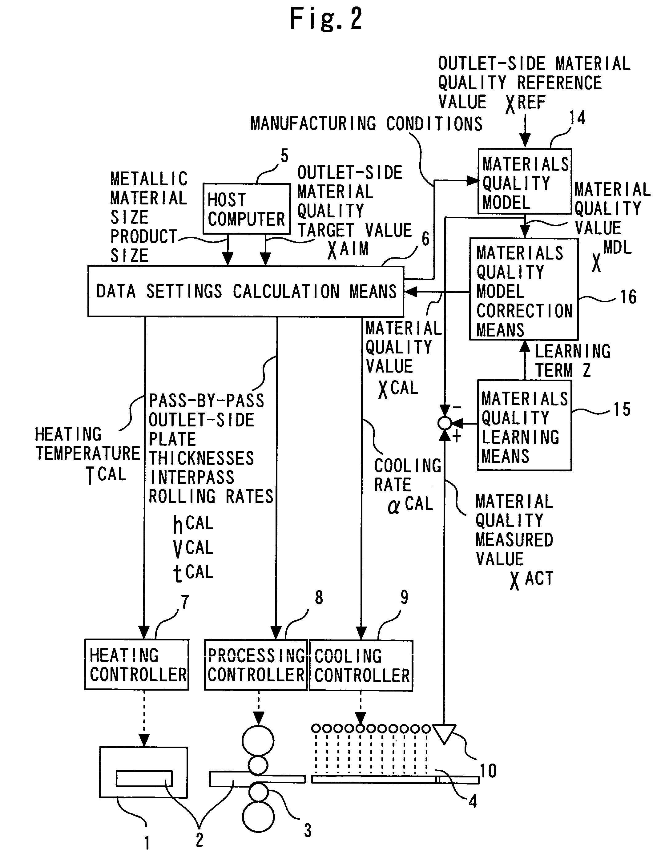
[0109]FIG. 2 is a block diagram showing a method and apparatus for controlling materials quality in a rolling, forging, or leveling process according to a second embodiment of the present invention.

[0110] Operation of a materials quality sensor 10, a heater 2, a processor 3, a cooler 4, a heating controller 7, a processing controller 8, and a cooling controller 9, is the same as in the first embodiment. In addition to target data on a metallic material size, on a product size, and on other factors, a material quality target value XAIM to be achieved at a measuring position of the materials quality sensor 10 is given from a host computer 5, as in the first embodiment. Manufacturing conditions are given from a data settings calculation means 6 to a materials quality model 14, and an outlet-side material quality reference value XRF is given from the host computer 5.

[0111] A materials quality learning means 15 compares a value XACT that has been measured by the materials quality senso...

third embodiment

[0122]FIG. 3 is a block diagram showing a method and apparatus for controlling materials quality in a rolling, forging, or leveling process according to a third embodiment of the present invention.

[0123] Operation of a data settings calculation means 6, a heating controller 7, a processing controller 8, a cooling controller 9, a heater 2, a processor 3, and a cooler 4, is the same as in the conventional method and apparatus underlying the present invention.

[0124] A materials quality sensor 10 is installed at any position upstream with respect to at least one of the heater 2, processor 3, and cooler 4 in an associated manufacturing line. The heater 2, processor 3, and cooler 4 downstream with respect to the materials quality sensor 10 can each be provided in a plurality of positions and arranged in any order.

[0125] In addition, any point on the upstream side with respect to the materials quality sensor 10 in the manufacturing line is defined as a materials quality control point. F...


PUM

PropertyMeasurementUnit
Grain sizeaaaaaaaaaa
Sizeaaaaaaaaaa
Waveaaaaaaaaaa

Abstract

The invention matches the material quality of a product to target data, even when a materials quality model is insufficient in prediction accuracy. Heating a metallic material, rolling, forging, or leveling the metallic material, and cooling the metallic material are each conducted at least once. Prior to manufacture of a metallic product of a desired size and shape, qualitative data of the metallic material are measured at a position by materials, quality sensor in a manufacturing line, and modifications based on measured data are made to heating, processing, or cooling conditions in at least one of the steps, upstream of the materials measured data sensor so that the quality of the metallic material at the measuring position agrees with target data.

Description

TECHNICAL FIELD [0001] The present invention relates to a method and apparatus for controlling materials quality in a rolling, forging, or leveling process. The above method and apparatus are intended to manufacture a product of a desired size and shape by conducting a heating process, a rolling, forging, or leveling process, and a cooling process each at least once for a metallic raw material. BACKGROUND ART [0002] The mechanical characteristics (e.g., strength, formability, and tenacity), electromagnetic characteristics (e.g., magnetic permeability), and other properties of metallic materials inclusive of ferroalloys and aluminum alloys vary not only with the chemical composition of the particular alloy, but also with its heating conditions, its processing conditions, and its cooling conditions. The composition of an alloy is conditioned by controlling an adding rate of constituent element(s). The lot sizes of products during quality governing, however, are too great to change an ...

Claims


Application Information

Patent Timeline
IPC IPC(8): C21D11/00
CPCB21B37/44B31B37/00B21B38/00B21B37/74B21B37/00
Inventor SANO, MITSUHIKOOHARA, KAZUHIKOTSUGENO, MASASHI
Owner TOSHIBA MITSUBISHI-ELECTRIC IND SYST CORP
Why Eureka
Eureka Blog
Learn More